Four Wheel Alignment Check

FRT No: 31002100

Note: This procedure is not specific to a particular alignment machine. Follow the alignment equipment manufacturer's instructions for additional information and safety instructions.

Preparation

  1. Ensure that the following are within Tesla-approved specifications before continuing to the next step of this procedure:
    • Wheel offset
    • Tire size (refer to the tire and loading information label)
    • Tire wear
    • Tire pressure
    Caution: Do not perform this procedure on a vehicle that has non-OEM wheels, incorrect wheel offset, tire(s) with less than 4/32 in (3 mm) tread, or incorrect tire pressure.
  2. Use a diagnostic cable with an extension cable to connect a laptop with Toolbox to the vehicle.
    Note: The extension cable is necessary so that the laptop can be accessed from outside of the vehicle during this procedure.
  3. Perform the following steps if the fasteners that secure the steering rack, steering column, intermediate shaft, tie rods, or front subframe have been loosened or removed:
    1. In Toolbox, open the Lock to Lock Test - Angle view.
    2. Perform the test as directed by Toolbox.
      Note: Do not disconnect the laptop; it will be used in later steps.
  4. Turn off the climate control system.
  5. Ensure that all pins are inserted into the slip plates and turn plates on the alignment machine.
  6. Set the suspension to “Standard".
  7. Drive onto the alignment rack. Stop the vehicle 1-2 ft (300-600 mm) before the turn plates so that the rolling compensation can be performed in a later step.
  8. Shift into Park.
    Note: Do not change the suspension height yet.
  9. On the touchscreen, select FACTORY > STW ANGLE.
  10. Exit the vehicle with the laptop still connected to Toolbox.
  11. Place the laptop on a cart or other surface that is a safe distance from the alignment rack.
    Caution: Placing the laptop on the alignment rack can result in damage in later steps.
  12. Place chocks on both sides of the driver's side rear tire.
  13. Complete the following steps to ensure that the drive rail stays on for the remainder of this procedure:
    1. Enter the vehicle.
    2. Buckle the driver’s seatbelt.
    3. Shift into Neutral.
    4. Use a pen or screwdriver shaft to manually close the latch assembly on the driver’s door while it is open.
      Note: The latch is fully closed when it clicks twice.

Alignment Check

  1. Raise the alignment platform until it is clear of all 4 rack locks.
  2. Lower the alignment platform onto the rack locks and ensure that it is level.
  3. Secure all 4 alignment optical targets.
  4. Perform the rolling compensation.
  5. Remove the pins from the slip plates and turn plates.
  6. Air suspension only: Check the ride height:
    • If the fasteners that secure a subframe, ride height sensor, ride height sensor bracket, front upper control arm, or rear camber link have been loosened or removed:
      1. Select Normal in the Toolbox "Air Suspension Leveling" panel.
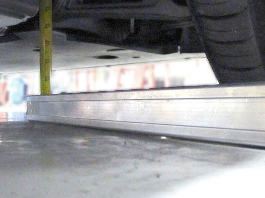
      2. Place the measuring tool on the platform, then measure the distance from the platform to the bolt head (front corners) or tip of the bolt (rear corners).
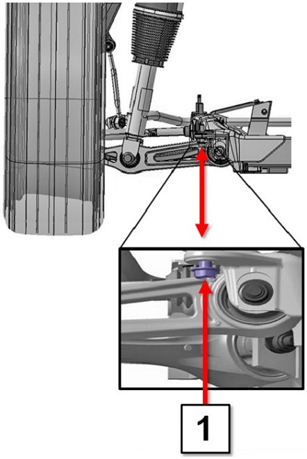
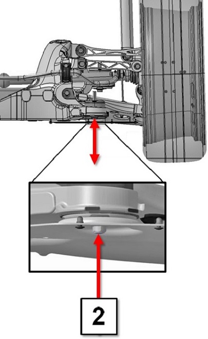
        Front Suspension (rearmost subframe bolt, rear view, left side) Rear Suspension (front subframe bolt, front view, left side)

        View large image.

        View large image.

        1 Measure to center of bolt head
        2 Measure to center of bolt end tip
      3. Record the measured ride heights for each corner.
      4. In Toolbox, refer to the "Ride Height" panel. Subtract the ride height shown by Toolbox from the measured ride height for each corner. Refer to the example below.
        Note: If the Toolbox ride height is a negative number, add it to the physical measurement. If the Toolbox ride height is a positive number, subtract it from the physical measurement.
        Table 1. Example Only
          Left Front Right Front Left Rear Right Rear
        Physical measurement 213 208 140 143
        Toolbox ride height -2 +3 +1 -4
        Total (physical measurement - Toolbox ride height) 215 205 139 147
      5. Compare the total heights of each corner to the ride height specifications: General Information > Technical Data > Wheel Alignment .
          Left Front Right Front Left Rear Right Rear
        Total from previous step 215 205 139 147
        Specification 213.5 +/- 5 213.5 +/- 5 144 +/- 5 144 +/- 5
        Result Pass Fail Pass Pass
        Note: The specification shown is an example. Refer to General Information > Technical Data > Wheel Alignment for the proper specifications.
        Note: The specification shown is an example. Refer to General Information > Technical Data > Wheel Alignment for the proper specifications.
      6. If the total of any value is outside of the specifications, perform a ride height calibration (refer to procedure).
        Note: The ride height calibration is not included in the four wheel alignment check correction code. Add the ride height calibration correction code separately.
    • If none of the above fasteners have been loosened or removed:
      1. In Toolbox, select Views > Suspension > Air Suspension Leveling, then run the Cycle Heights High > Normal routine.
      2. In Toolbox, select Views > Suspension > Ride Height.
      3. Check that each level is between -5 mm and +5 mm.
      4. If any level is not between -5 mm and +5 mm, run the Cycle Heights High > Normal routine again.
      5. If any level is not between -5 mm and +5 mm, run the Cycle Heights High > Normal routine again.

Note: Do not bump or pull on the vehicle for the remainder of this procedure; this could bring the ride height values out of specification.

  1. Install the brake pedal depressor.
  2. Perform a caster sweep without sitting inside or leaning on the vehicle.
  3. Turn the steering wheel so that the steering wheel angle displayed on the touchscreen is 0.0 degrees, then install the steering wheel holder.

Note: If the alignment machine indicates that all parameters are within specification, the vehicle passes the alignment check. Continue to the next step.
Note: If the vehicle fails the alignment check, perform a full alignment (refer to procedure) and add the appropriate correction code for "Four Wheel Alignment - Adjust Only":
  • Air Suspension:31002100
  • Coil Suspension:31002200

  1. Transfer the PDF of the alignment results from the alignment machine and attach it to the repair order.
  2. Remove the brake pedal depressor.
  3. Reinstall all slip plate pins and turn plate pins.
    Tip: Install the forward slip plate pins before installing the rearward slip plate pins.
  4. Remove all 4 alignment optical targets.
  5. Enter the vehicle.
  6. Press the brake pedal and shift into Park.
  7. Remove the wheel chocks.
  8. Remove the vehicle from the alignment rack.