Removal
Warning: Only technicians who have been
trained in High Voltage Awareness are permitted to perform this procedure.
Proper personal protective equipment (PPE) and insulating HV gloves with a
minimum rating of class 00 (500V) must be worn any time a high voltage cable is
handled. Refer to Tech Note TN-15-92-003, "High Voltage Awareness Care Points"
for additional safety information.
Note: This procedure describes how to replace the fuses in the Wall Connector. For
information on upgrading the fuses from 100A to 200A, refer to SB-13-50-004,
High Power Wall Connector Fuse Upgrade.
-
Remove the screws (x2) that secure the cover of the Wall Connector to the
casing (torque 1.1 Nm).

-
Release the front cover by pulling it forward far enough to disconnect the
ribbon cable from the cover. Disconnect the ribbon cable from inside the
main enclosure to fully remove the front cover.
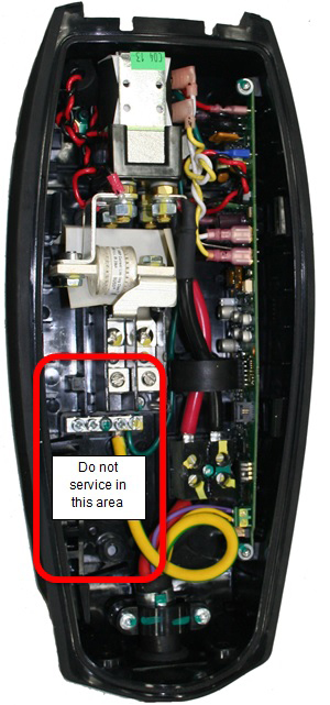
Caution: When removing the front cover, do not damage the ribbon cable. Disconnect the ribbon cable before fully releasing the front cover.Caution: Do not service the area from the utility input to the left terminal blocks. This wiring is considered house wiring, and must be connected and serviced by a certified electrician.

-
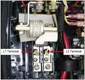
Use a properly rated HV voltmeter or multimeter to check for AC voltage
between terminals L1 and L2. Ensure that the correct power breaker has been
turned off to de-energize the Wall Connector.
-
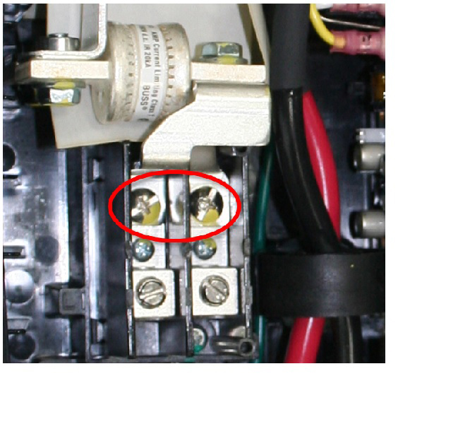
Remove the screws that connect the bus bars to terminals L1 and L2.

-
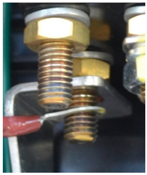
Use a 13 mm socket wrench to remove the nuts that fasten the bus
bars.

-
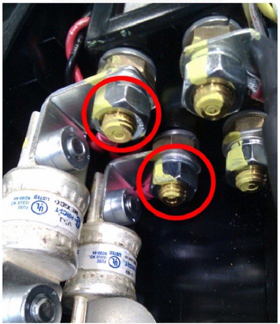
Before removing the fuse/bus bar assemblies completely, note the order of
the components from bottom to top: nut, split washer, wire lug, bus
bar.
Caution: Take note of the color configuration of the wiring to the contactor before removal. Ensure that all wiring is installed to the same location it was before removal.

-
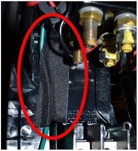
Ensure that the green ground wire is secured to the back of the Wall
Connector. If it is not, use wire harness tape or other high temperature
resistant tape to secure it to the back of the Wall Connector.