Removal
-
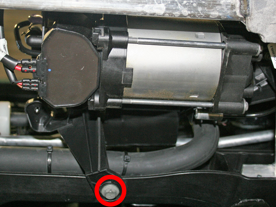
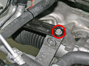
Release the bolt that secures the air compressor bracket to the front carrier
(torque 5.5 Nm).
Note: The remaining 2 bolts that secure the bracket are removed in a later step.

-
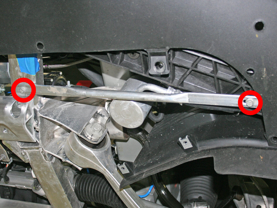
If equipped: On each side of the vehicle, release the bolts (x2) that
secure the staybar (torque 11 Nm).

-
Rear wheel drive vehicles only: Remove the nuts (x4) that secure the A/C
compressor bracket to the subframe (torque 8 Nm).

-
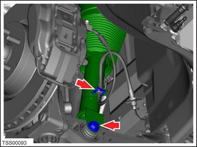
Remove the bolts (x2) that secure the chiller to the subframe (torque 12
Nm).
-
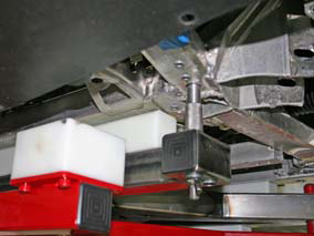
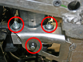
Remove the nuts (x2), washers (x2), and rubber grommet that secure the ABS pump
(torque 9 Nm).
-
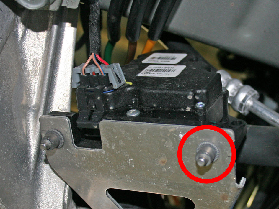
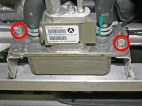
Release the front bolt that secures the radiator bypass 3-way coolant valve to
the subframe (torque 5 Nm).
Note: The remaining bolt that secures the 3-way valve is removed in a later step.

-
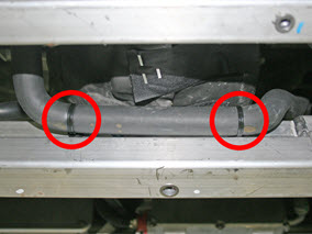
Dual motor vehicles only: Release the clips (x2) that secure the coolant
hose to the subframe.
-
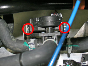
Release the remaining bolts (x2) that secure the chiller bypass 3-way valve to
the subframe (torque 5 Nm).
-
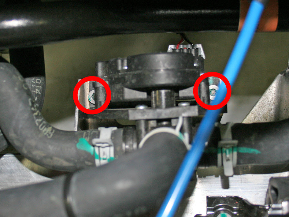
Disconnect the 2 harnesses from the steering rack.

-
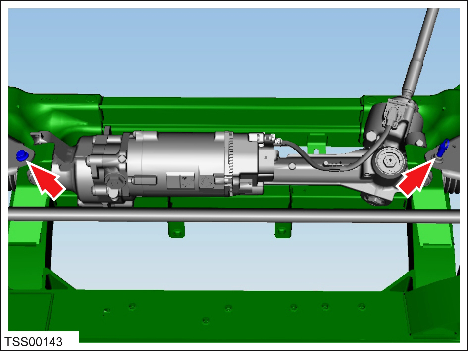
On each side of the vehicle, release the bolt that secures the steering brace to
the subframe (torque 26 Nm):
- RWD vehicles:
- Dual motor vehicles:
- RWD vehicles:
-
On both sides of the vehicle, restrain the tie rod ball joint pin, then remove
the nut that secures the tie rod end to the knuckle (torque 103 Nm).
Caution: To prevent ball joint damage, always hold the ball joint pin with a wrench while loosening or tightening the lock nut.

-
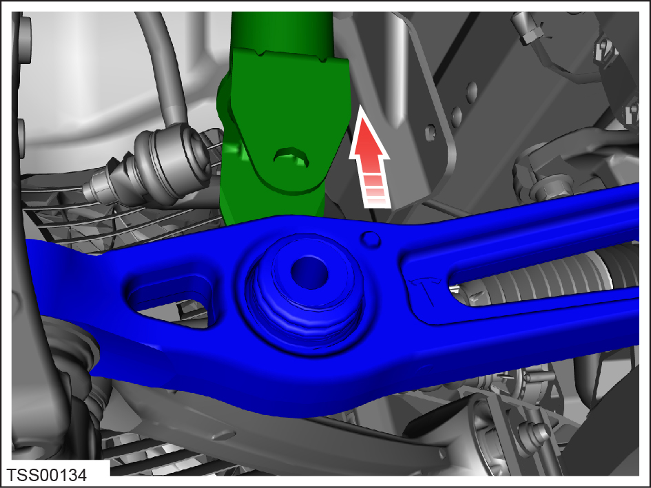
Remove the bolt and nut that secure the front shock absorber to the rear lower
control arm (torque 140 Nm).
-
Release the shock absorber from the lower arm.

-
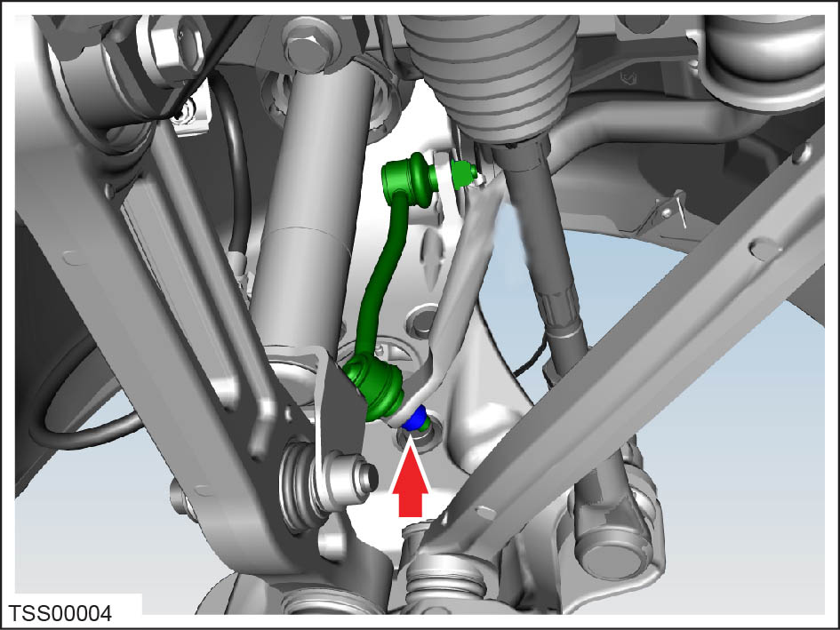
On each side of the vehicle, remove and discard the nut that secures the sway
bar to the sway bar end links (torque 70 Nm).
Caution: Replace all nylon-insert locknuts.

-
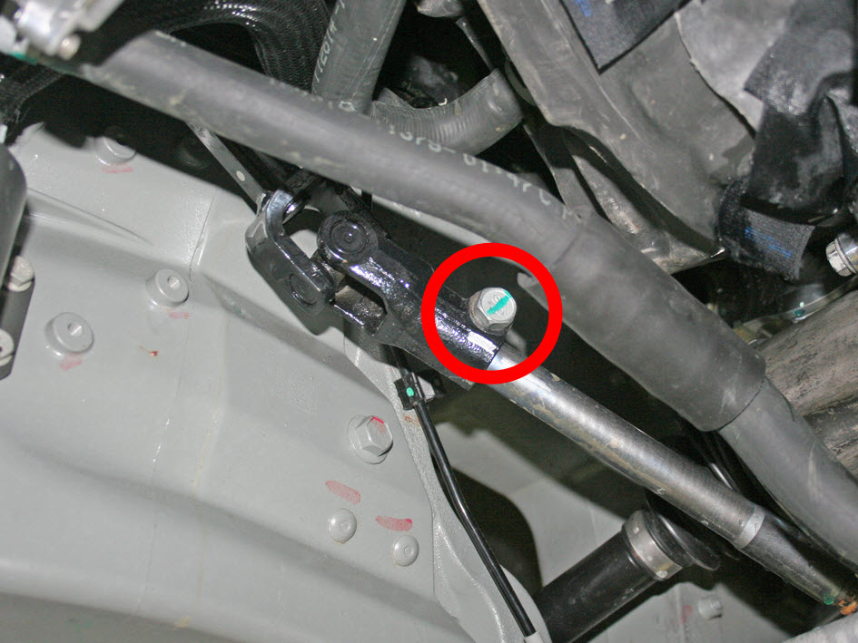
Remove the bolt that secures the lower intermediate shaft to the steering rack
(torque 49 Nm).

-
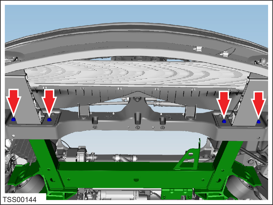
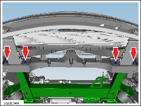
Remove the bolts (x4) that secure the front subframe to the bumper
carrier:
- Composite carrier: 7.5 Nm
- Magnesium carrier: 11 Nm
-
On each side of the vehicle, release the bolt that secures the steering brace to
the subframe (torque 26 Nm):
- RWD vehicles:
- Dual motor vehicles:
- RWD vehicles:
-
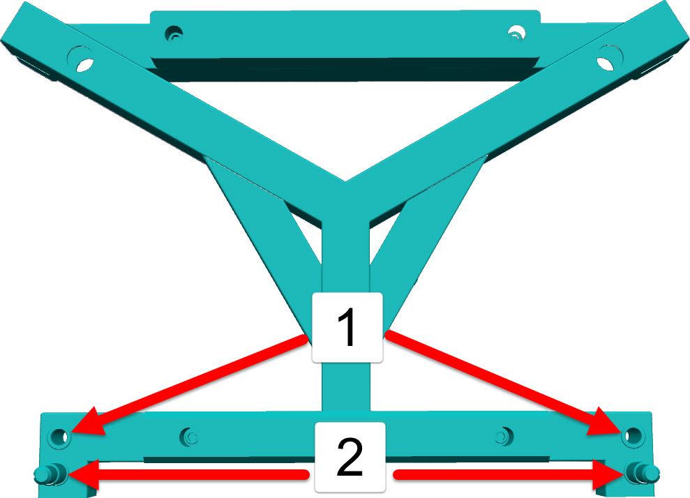
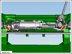
Install the locating pins in the appropriate location.
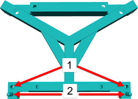
1 Rear wheel drive 2 Dual motor -
Have an assistant lower the vehicle. Guide the front subframe onto the
fixture.