FRT No: 16010700
Warning: Only technicians who have been
trained in High Voltage Awareness are permitted to perform this procedure.
Proper personal protective equipment (PPE) and insulating HV gloves with a
minimum rating of class 00 (500V) must be worn any time a high voltage cable is
handled. Refer to Tech Note TN-15-92-003, "High Voltage Awareness Care Points"
for additional safety information.
These instructions are for the 4th generation battery charger/discharger tool. The 4th generation tool has the following features:
- The serial number includes "G4"
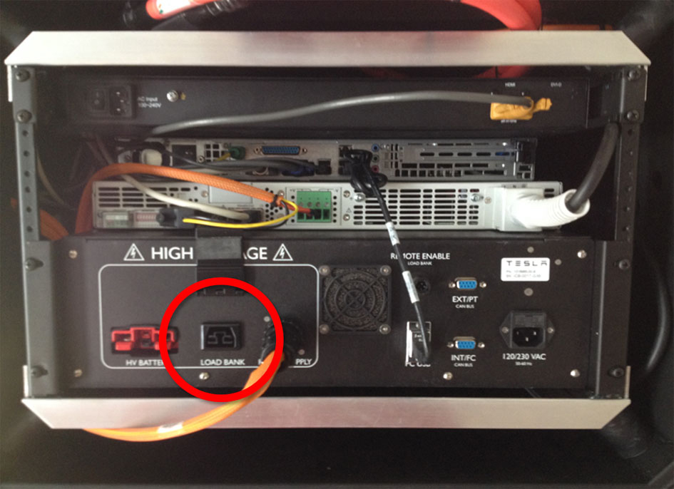
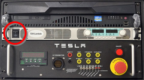
- The charger/discharger tool has a rectangular load bank connector
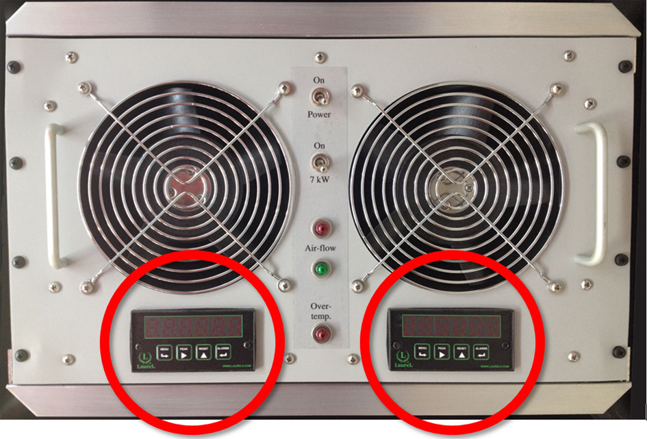
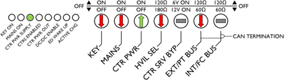
- The load bank has a display below each fan