Removal
Warning: Only technicians who have been
trained in High Voltage Awareness are permitted to perform this procedure.
Proper personal protective equipment (PPE) and insulating HV gloves with a
minimum rating of class 00 (500V) must be worn any time a high voltage cable is
handled. Refer to Tech Note TN-15-92-003, "High Voltage Awareness Care Points"
for additional safety information.
-
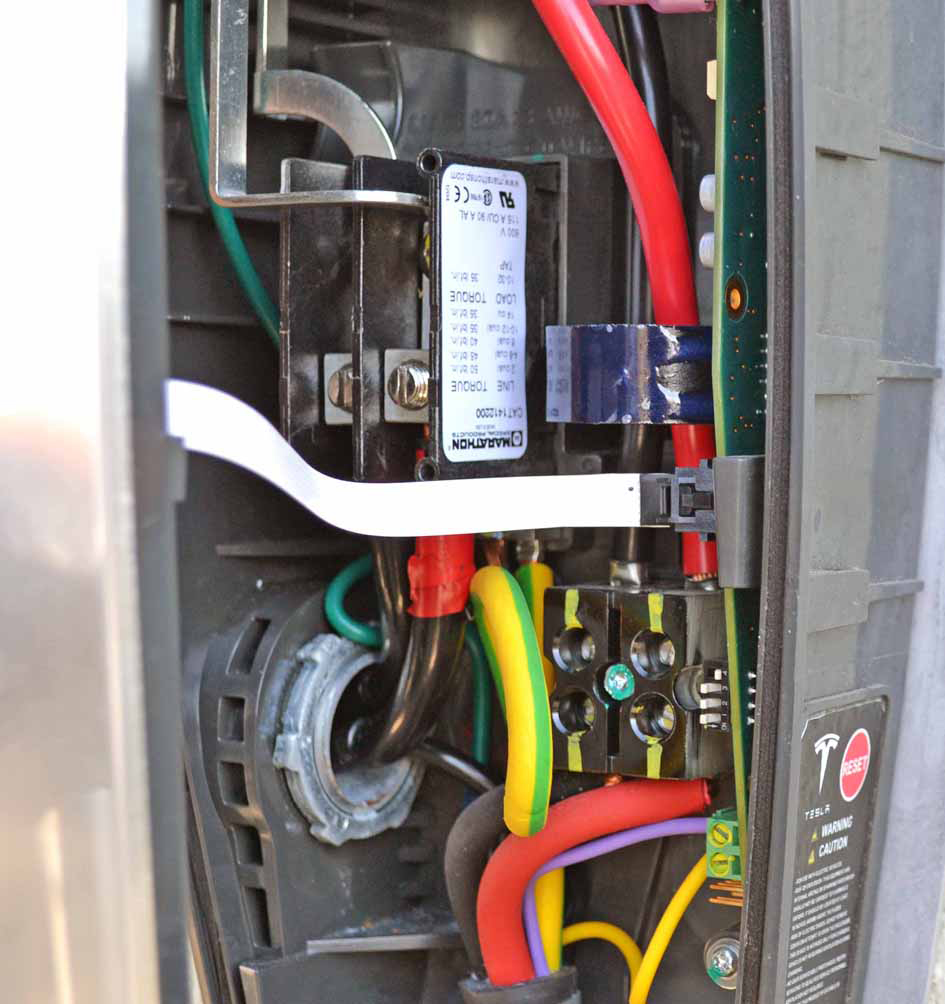
Remove the screws (x2) and washers (x2) that secure the cover of the Wall
Connector to the casing (torque 1.1 Nm).

-
Remove the front cover of the Wall Connector; disconnect the white flex cable
from the interior.
Caution: When removing the front cover, do not damage the ribbon cable. Disconnect the ribbon cable before fully releasing the front cover.

-
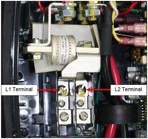
Use a properly rated voltmeter or multimeter to check for AC voltage between
terminals L1 and L2. Ensure that the correct power breaker has been turned off to
de-energize the Wall Connector.
-
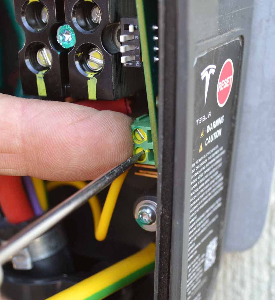
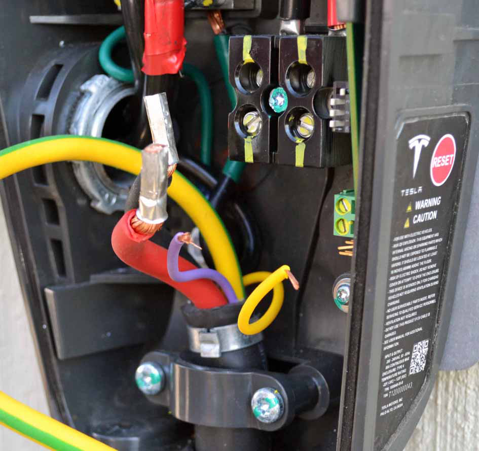
Loosen the screw that secures the yellow and green grounding wire (torque 2.3
Nm). Remove the grounding wire.
-
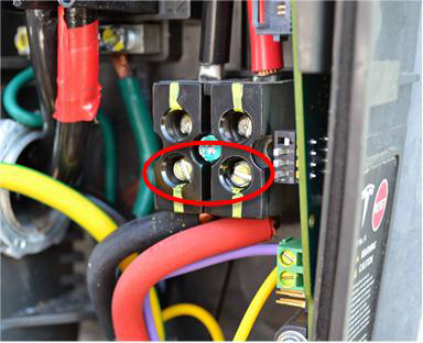
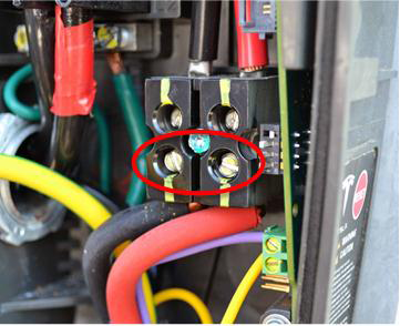
Loosen the screws (x2) that secure the red and black L1 and L2 wires (torque
17.2 Nm).
Caution: The ferrules on the ends of the L1 and L2 wires are one-time-use only. The ferrules or the handle and cable assembly must be replaced if they have been previously installed.
-
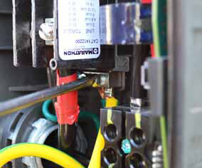
While holding the green terminal block in place with a finger, loosen the screws
(x2) that secure the purple and yellow wires (torque 1.1 Nm) to the block. Remove
the wires.
Note: Make sure to hold the terminal block in place so it does not bend away from the printed circuit board.

-
Remove the red and black L1 and L2 wires.

-
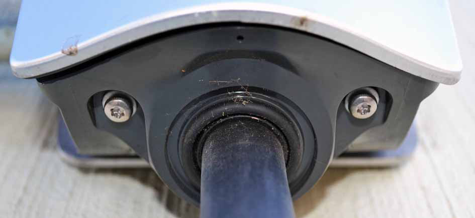
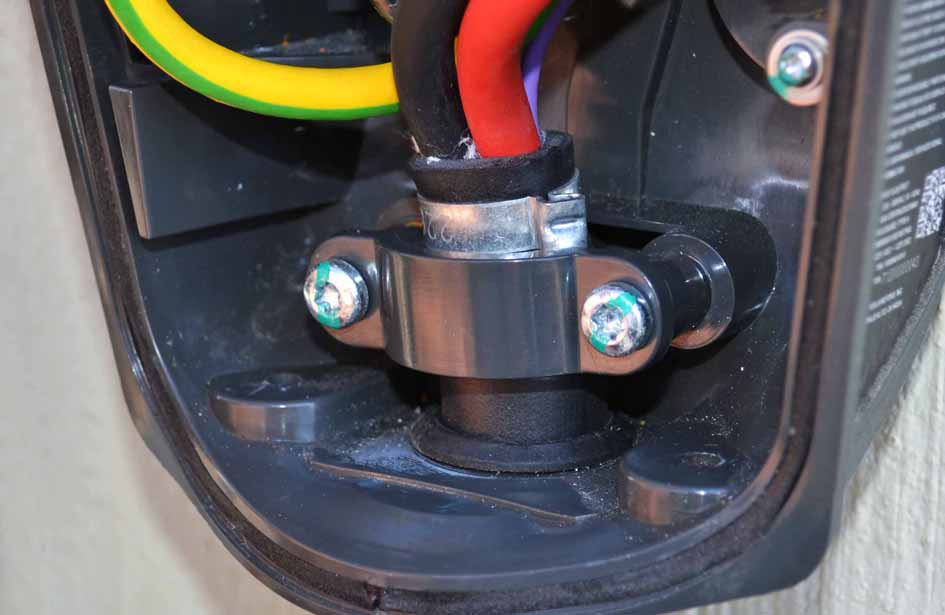
Remove the screws (x2) that secure the plastic clamp to the casing (torque 3.4
Nm).

-
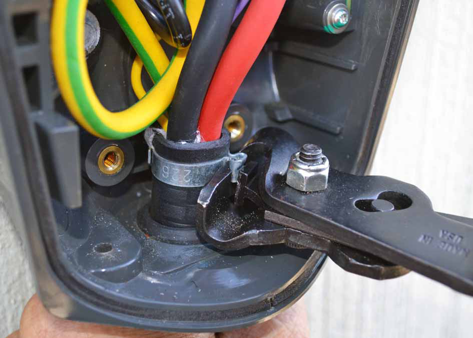
Use a diagonal cutter to cut the pinch clamp away from the cable.

-
Pull the cable down through the casing until the wires are free.