FRT No: 39012600
Note: This procedure assumes that the RH mount has been replaced, but that the shim
tools cannot be repositioned to verify proper clearance. If this happens, follow this
procedure to adjust the LH side motor mount.
-
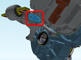
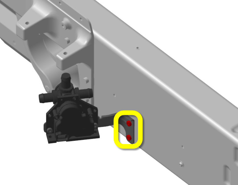
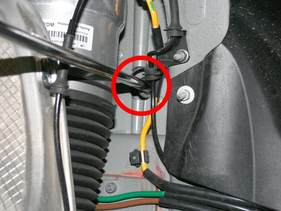
Release the 2 bolts that secure the 4-way valve bracket to the body.
-
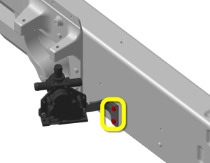
Looking upward through the wheewell, inspect the rear of the LH motor mount. Note
whether it has a backing plate that secures the nuts; this information will be used
later in the procedure.
-
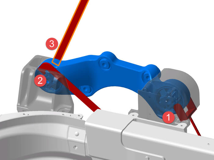
Position the LH strap:
Note: Work from the underhood area while an assistant works from the LH wheelwell.
-
Slide the strap between the LH motor mount and the front drive unit.
-
Slide the strap between the LH motor mount and the front drive unit.
-
Loosen the 2 adjustment bolts on the LH mount until the weight of the motor shifts
onto the strap.
Note: If the LH motor mount does not have a backing plate, have an assistant use a 15 mm wrench to restrain the nuts on the rear of the motor mount while loosening the bolts.

-
Loosen the 4 bolts that secure the RH motor to the mount.
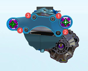
- Working from the underhood area, loosen the forward upper bolt.
- Working from the underhood area, loosen the forward lower bolt.
- Working from the RH wheelwell, loosen the rear upper bolt.
- Working from the RH wheelwell, loosen the rear lower bolt.
-
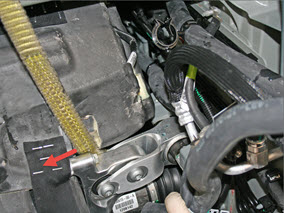
Working from the RH wheelwell, use socket wrench with an extension to loosen the 2
bolts that secure the mount to the body.
-
Loosen the rear bolt and washer.
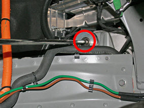
-
Loosen the front bolt.

-
Loosen the rear bolt and washer.


Note: The motor can now be moved to position the shim tools appropriately.
-
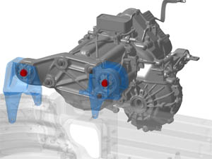
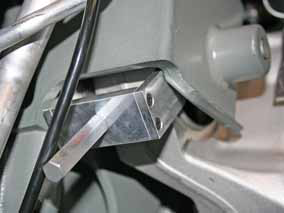
Position the 3 shim tools in between the RH motor mount and body.
Note: These tools ensure proper clearance. Leave them in place until prompted to remove, after all 6 bolts for the mount are fully torqued.

-
Working from the underhood area, position the 2-pronged shim around the RH
motor mount front bushing.
-
Working from the underhood area, position the 2-pronged shim around the RH
motor mount front bushing.
-
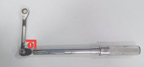
Attach the 15 mm ratchet tool to a torque wrench.
Caution: Ensure that the attachment is 90 degrees perpendicular to the torque wrench when using the tool.
-
Working from the underhood area, fully torque the 4 bolts that secure the motor to
the mount (torque 75 Nm).

- Working from the underhood area, use the ratchet and torque wrench to secure the upper front bolt.
- Working from the wheewell, secure the lower rear bolt.
- Working from the wheewell, secure the upper rear bolt.
- Working from the underhood area, use the ratchet and torque wrench to secure the lower front bolt.