Removal
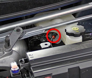
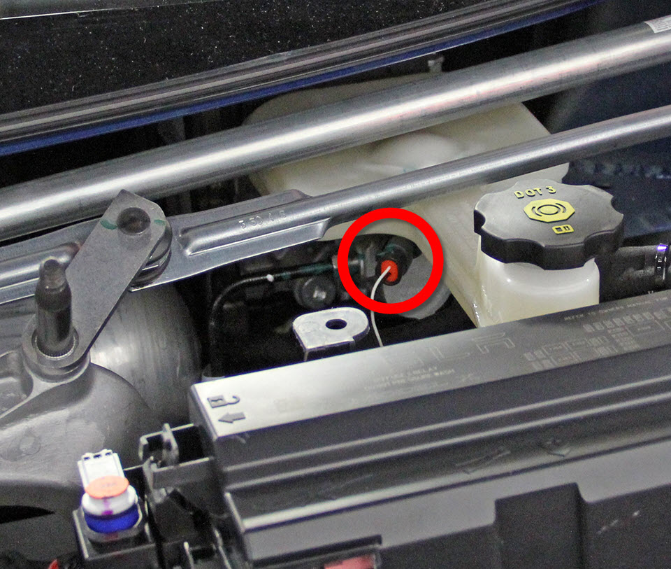
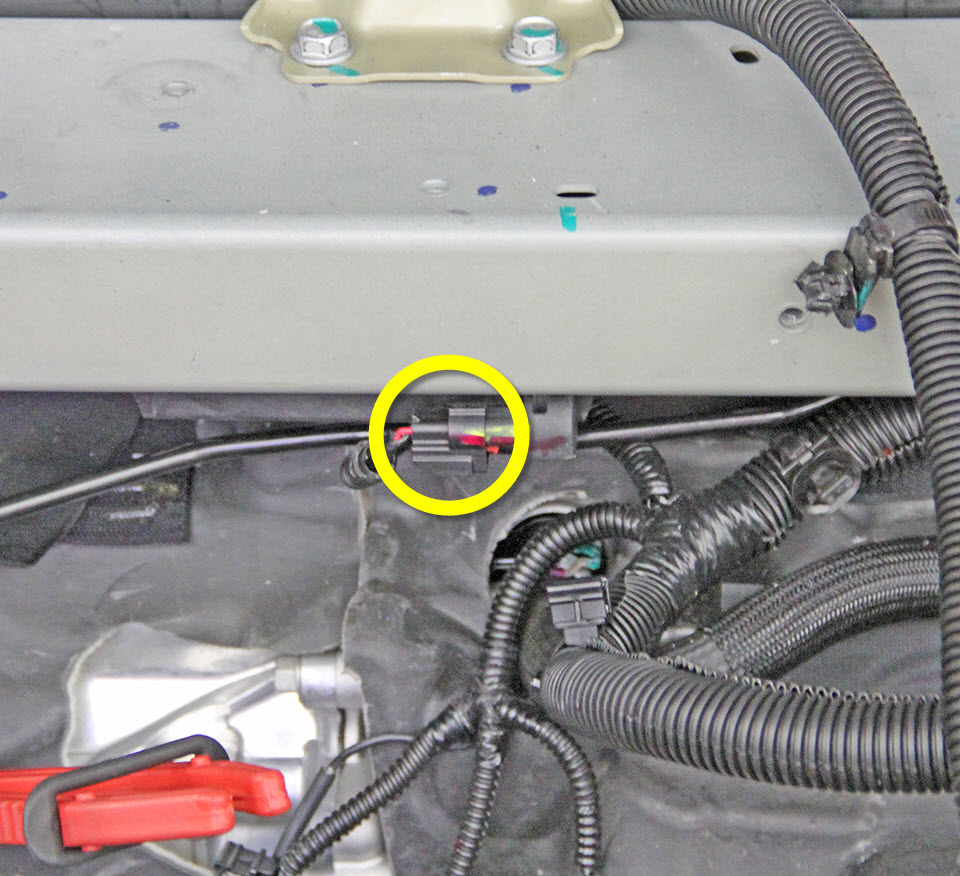
- Disconnect the brake fluid level sensor electrical connector.
-
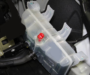
Move the coolant reservoir out of the working area:
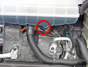
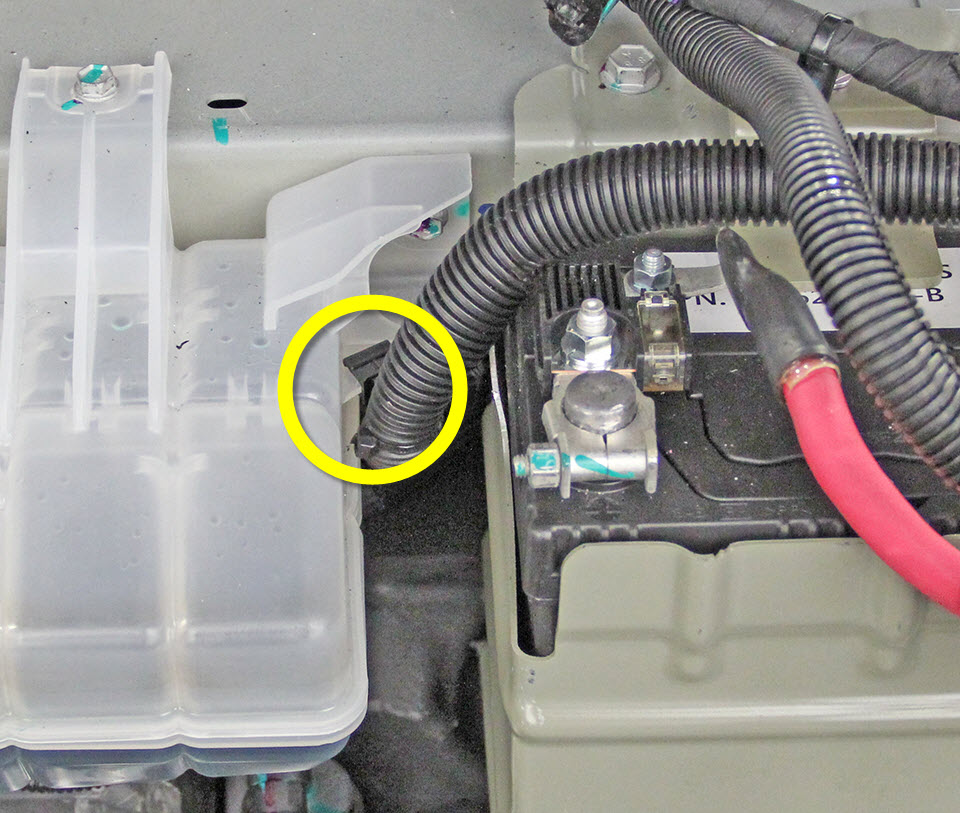
- Release the 12V harness clip from the coolant reservoir.
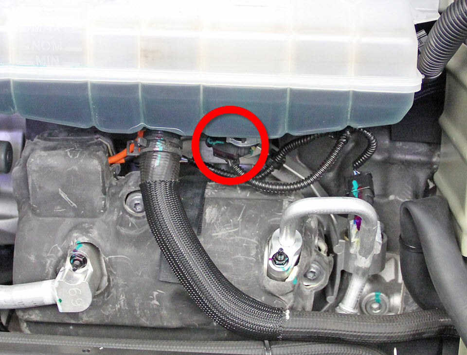
- Disconnect the coolant fluid level sensor electrical connector.
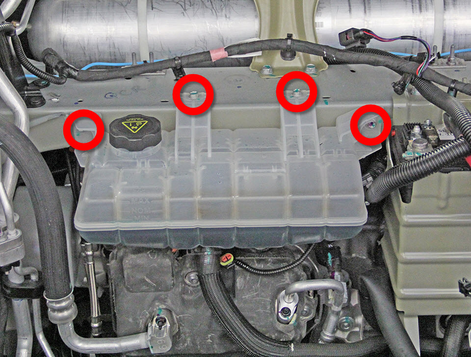
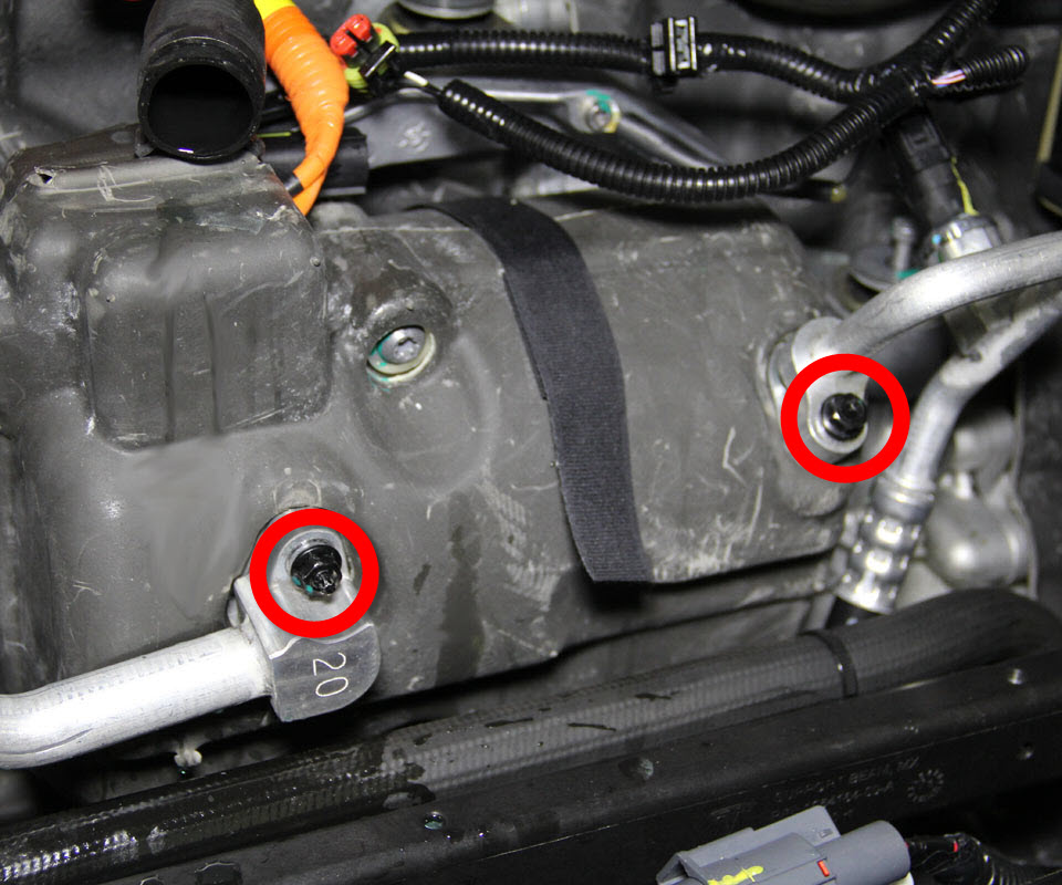
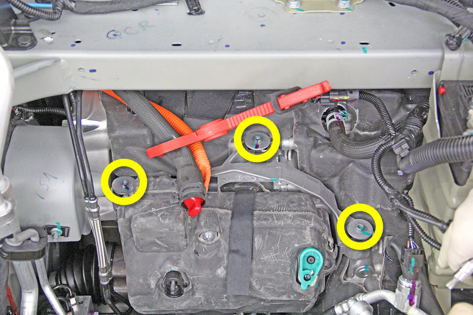
- Remove the bolts (x4) that secure the coolant reservoir to the front crossmember (torque 6 Nm).
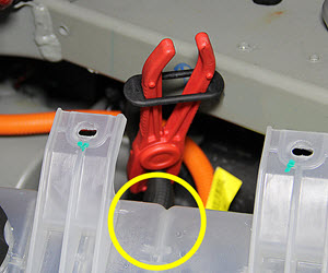
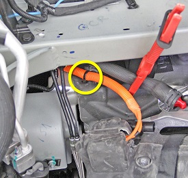
- Clamp the coolant hose at the rear of the coolant reservoir.
- Plug the coolant hole then carefully move the reservoir to the LH side of the frunk.
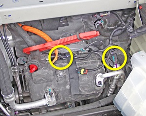
- Disconnect the low voltage electrical connector from the A/C compressor and the electrical connector from the high pressure pipe.
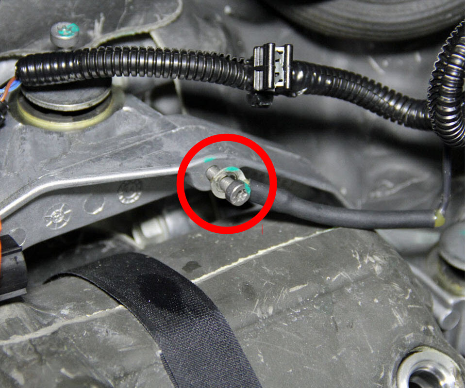
- Remove the screw that secures the ground strap to the compressor bracket (torque 8 Nm).
- Release the nuts (x2) that secure the A/C lines to the compressor (torque 10 Nm).
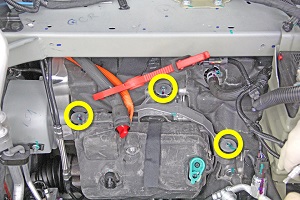
- Have an assistant support the compressor. Release the bolts (x3) that secure the A/C compressor bracket to the front drive unit (torque 10 Nm).
- Release the push clip that secures the A/C compressor HV cable to the body of the vehicle.
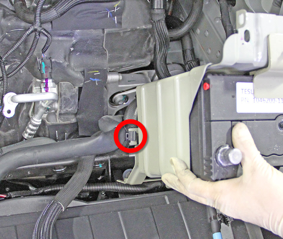
- Release the edge clip that secures the coolant hose to the battery cage. Remove the battery and battery cage from the vehicle.
-
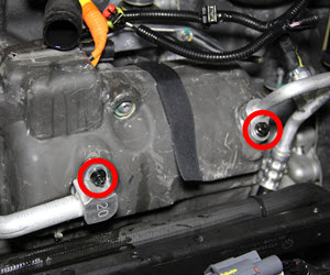
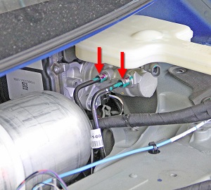
Release the flare fittings (x2) that secure the front and rear hydraulic
lines to the master cylinder (torque 18 Nm).
Caution: If brake fluid is spilled on a painted surface, wash off immediately with clean water.
-
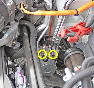
Release the flare fittings (x2) that secure the front and rear hydraulic
lines to the ABS module (torque 23 Nm).
Caution: If brake fluid is spilled on a painted surface, wash off immediately with clean water.
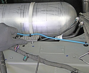
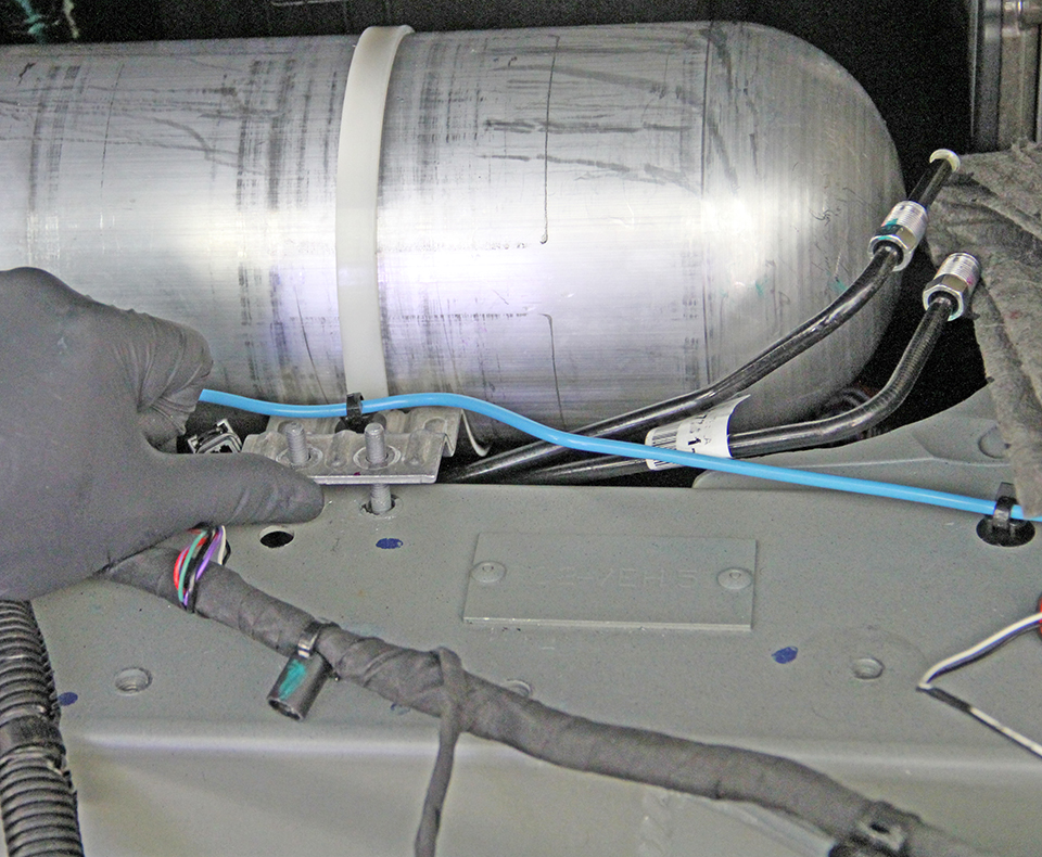
- Disconnect the electrical connector from the passive entry antenna on the bottom of the crossmember.
- While carefully lifting up on the LH side of the air tank reservoir (if equipped), maneuver the brake lines out from the bottom of the crossmember.


