Warning: If the 12V power supply is disconnected, do not attempt to open any doors with door glass in closed position. Failure to follow this instruction could result in door glass shatter.
                Note: Before disconnecting the 12V power supply, ensure that the
                    driver’s door window is fully open. Failure to follow this instruction could
                    result in vehicle lockout.
             
             
            - 
                    Remove the RH lower instrument panel assembly 
                            (refer to procedure).
                
 
- 
                    Remove the lower driver's side dash trim  (refer
                            to procedure).
                
 
- 
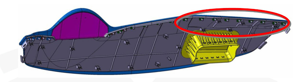
                    Remove the screws (x3) that secure the top of the glove box (torque 2
                        Nm).


- 
                    Remove the screw that secures the LH side of the top pad assembly (torque 1
                        Nm).


- 
                    Repeat the previous step on the RH side of the top pad assembly.
                
 
- 
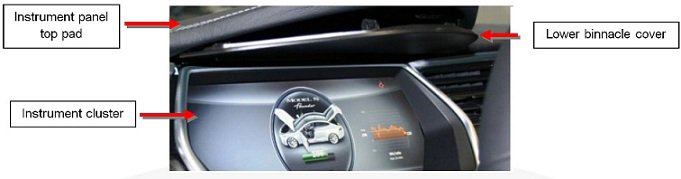
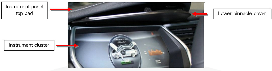
                    Remove the lower binnacle cover.


- 
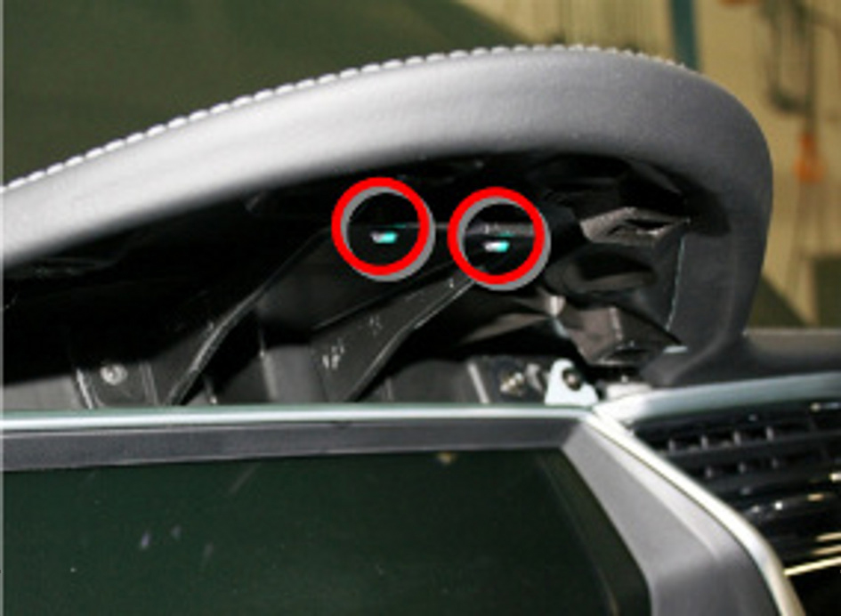
                    Remove the screws (x2) beneath the lower binnacle cover that secure the IP
                        top pad to the IP carrier (torque 1 Nm).


- 
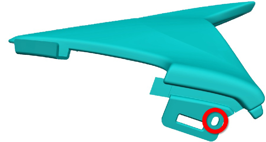
                    Lower the steering column and remove the steering column gap hider by
                        releasing the trim clips (x2).


- 
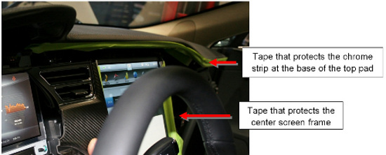
                    Cover the aluminum strips at the base of the top pad and around the center
                        screen with protective tape.
                    
                        Caution: If the aluminum strips are not covered
                with tape, they may be damaged when the top pad is removed in later steps.


- 
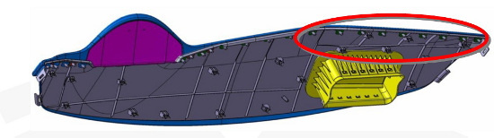
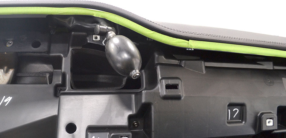
                    Gently lift up on the rightmost edge of the instrument panel top pad enough
                        to allow room for a trim pry tool to release the rightmost clip. Repeat this
                        process working from right to left, releasing one trim clip at a time until
                        just to the right of the center screen.
                    
                        Caution: Take care not to damage
                    component(s).
                        Note: Lifting with an inflatable wedge is recommended to reduce
                            the risk of bending the top pad. Place the inflatable wedge above the
                            vent outlet at the right side of the touchscreen.


- 
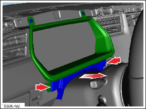
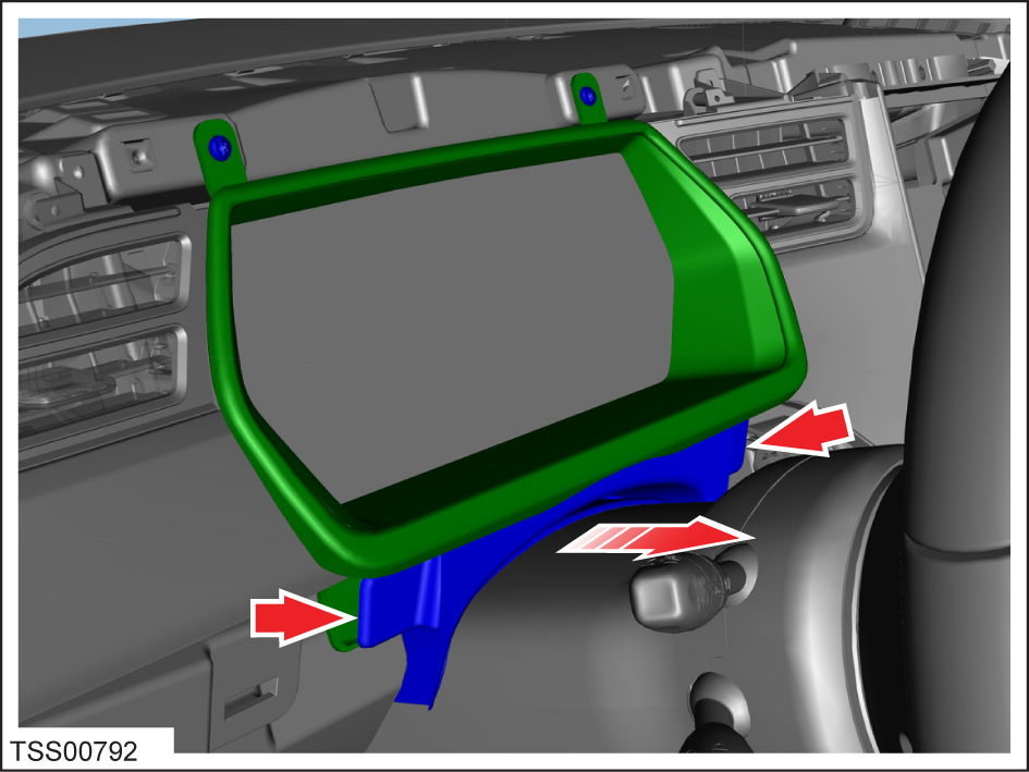
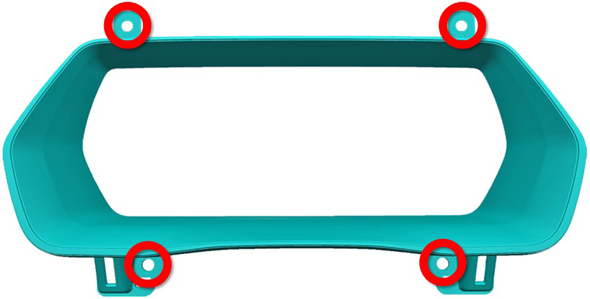
                    Remove screws (x4) that secure the instrument cluster bezel (torque 2
                        Nm).
                    
                        Note:  Components have been removed
                    in this graphic to aid clarity.


- 
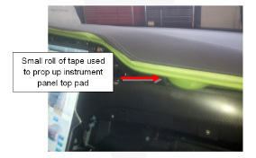
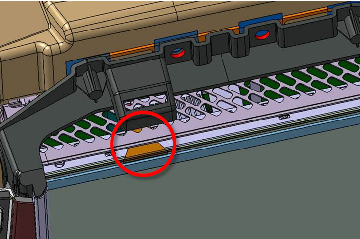
                    Gently lift up on the right side of the instrument panel top pad (no more
                        than 15 mm) and use a small wedge or other object to prop up the right side
                        of the top pad.
                    
                        Caution: Take care not to damage
                    component(s).


- 
                    Gently lift up on the leftmost edge of the instrument panel top pad to
                        allow room for a prying trim stick to release the leftmost clip. Repeat this
                        process working from left to right, releasing one trim clip at a time until
                        just to the left of the center screen.
                    
                        Caution: Take care not to damage
                    component(s).
                        Note: Lifting with an inflatable wedge is recommended to reduce
                            the risk of bending the top pad. Place the inflatable wedge above the
                            vent outlet at the left side of the touchscreen.


- 
                    Gently lift up on the left side of the instrument panel top pad (no more
                        than 15 mm) and use a small wedge or other object to prop up the left side
                        of the top pad.
                    
                        Caution: Take care not to damage
                    component(s).
                     
                 
- 
                    Use a prying trim stick to release the trim clips directly above the center
                        screen.
                    
                        Caution: Do not scratch or damage the printed flexible circuit
                            (PFC) when releasing the trim clips above the center screen.


- 
                    Use a prying trim stick to release the remainder of the clips, alternating
                        between the LH and RH sides.
                    
                        Caution: Take care not to damage
                    component(s).
                     
                 
- 
                    With an assistant, carefully lift up on both sides of the instrument panel
                        top pad until there is a small gap.
                    
                        Caution: Take care not to damage
                    component(s).
                        Note: Do not attempt to completely remove the instrument panel top
                            pad.
                     
                 
- 
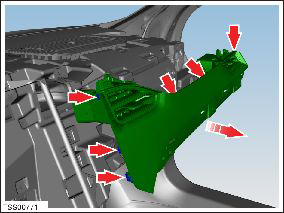
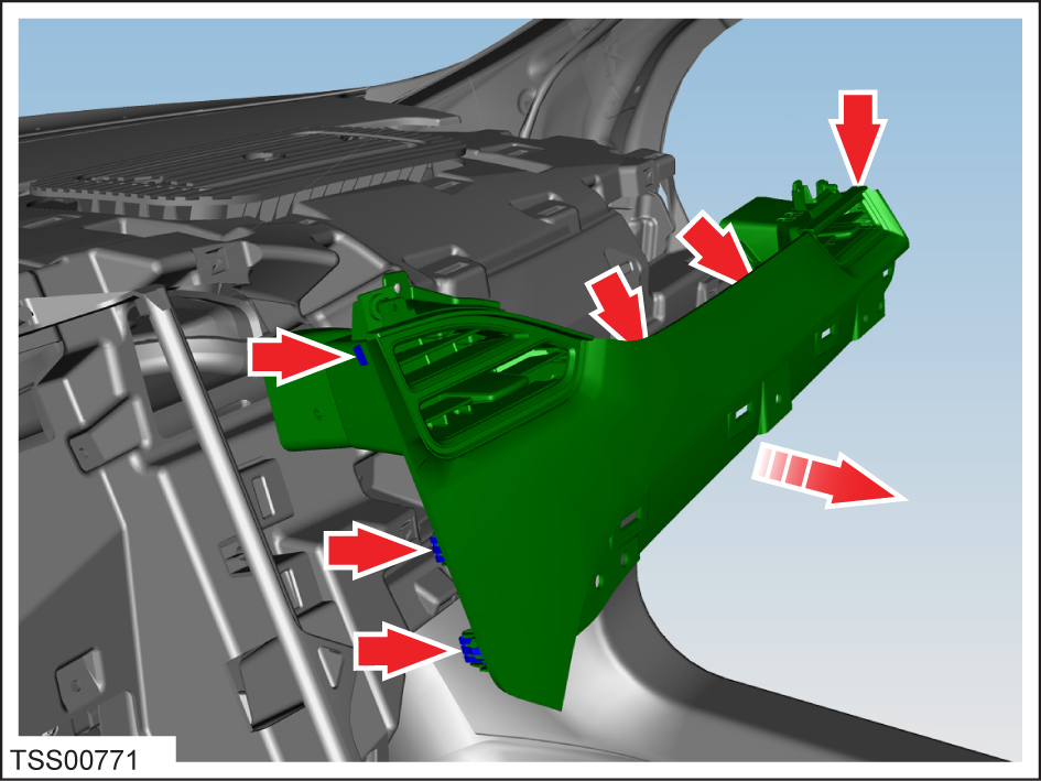
                    Remove the driver's inner trim and vent assembly by removing the screws
                        (x2) (torque 1 Nm) and clips (x3) that secure the vent and trim panel.


- 
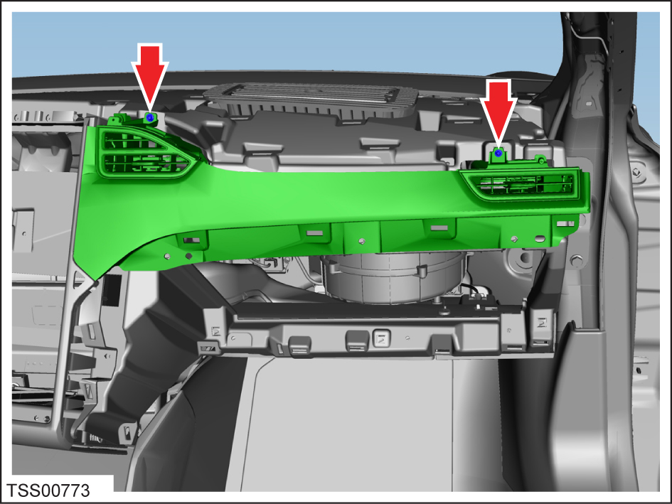
                    Remove the screws (x2) that secure the face vents to the carrier (torque 2
                        Nm).


- 
                    Use a suitable trim tool to carefully release the clips (x6) that secure
                        the IP finisher to the carrier.
                    
                        Caution: Take care not to damage
                    component(s).
                        Caution: Replace any broken clips.
                        Note:  Components have been removed
                    in this graphic to aid clarity.


- 
                    Disconnect 12V power.


- 
                    North American vehicles with LTE: Put on an ESD wrist strap and
                        connect it to chassis ground.
                    
                        Caution: Failure to ground to the chassis of the vehicle can
                            result in damage to the connectivity board.
                     
                 
- 
                    If equipped, remove the ground strap from the top of the MCU.
                
 
- 
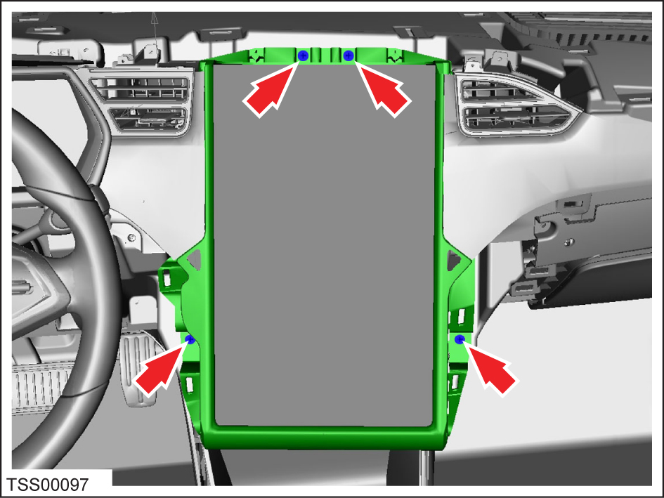
                    Remove the screws (x4) that secure the touch screen to the IP carrier
                        (torque 4.5 Nm).
                    
                        Caution: The top 2 screws might have washers (x3; 1 on the
                            driver's side screw, 2 on the passenger's side screw) on the backside of
                            the bezel. Secure the washers so that they do not fall behind the
                            instrument panel.


Caution: To avoid damage to the circuit board, fully depress the
                        connector release tab before pulling on a connector. Check all connectors on
                        the MCU/touch screen to make sure they are still securely attached to board.
                        If the connector bodies can be twisted, the MCU/touch screen must be
                        replaced.
                - 
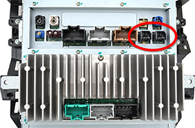
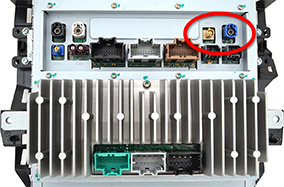
                    Gently tilt the top of the MCU/touch screen, then disconnect the Wi-Fi and
                        camera/Bluetooth harness connectors.
                    
                        Caution: To prevent damage, ensure there is sufficient slack in
                            the USB1 and USB2 wires. Excessive tension on these wires could damage
                            the connector bodies on the MCU/touch screen.
                        Note: The following image shows a revision D or earlier MCU/touch
                            screen.


- 
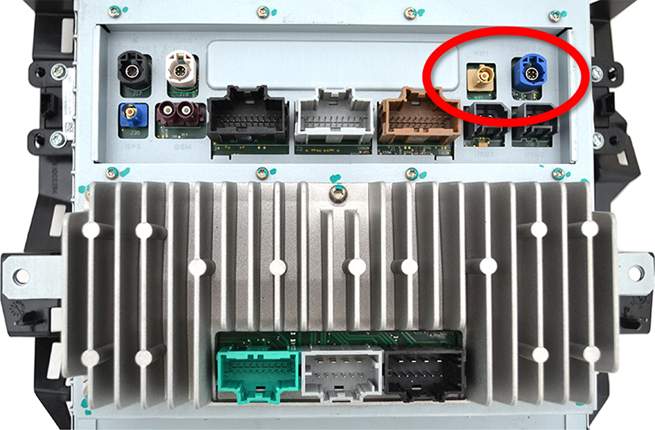
                    Disconnect the USB1 and USB2 harness connectors.
                    
                        Note: The following image shows a revision D or earlier MCU/touch
                            screen.


- 
                    Disconnect the remaining harness connectors.
                    
                        Caution: To prevent damage, make sure that the cables are
                            aligned correctly with no excessive twists or bends.
                     
                 
- 
                    Remove the ESD wrist strap.
                
 
- 
                    Remove the MCU/touch screen from the vehicle. Place it on a protective
                        surface.