Charge Port - Single Phase - Non-Motorized (Remove and Replace)

FRT No: 44012202

Note: This procedure describes how to remove and install the single phase charge port. If the vehicle is equipped with a 3 phase charge port, refer to procedure 44012102 (refer to procedure).
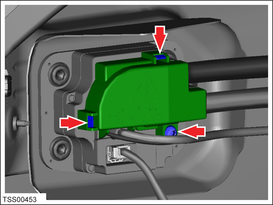
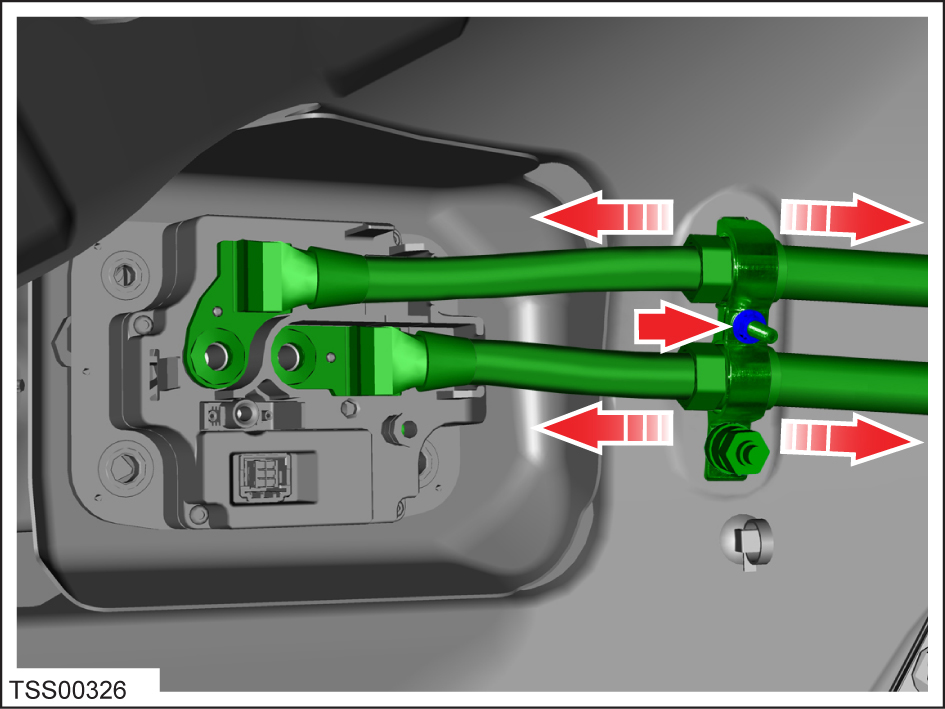
Warning: The high voltage harness must be removed from the charge port before the charge port is removed from the vehicle. Never remove the charge port from the vehicle without first disconnecting the high voltage harness. Failure to follow this requirement may result in serious injury or death due to exposure to high voltage. Only Service Technicians that have received and completed high voltage training are authorized to perform this service.

Special tool required for this procedure:

Supplier Part Number Description
Tesla 1020288-00-A TOOL,INSTALLATION,EV INLET,MDLS

Removal

  1. Perform the vehicle electrical isolation procedure (refer to procedure).
  2. Remove the LH trunk trim (refer to procedure) .
  3. Remove the screw and release the clips (x2) from the HV inlet cover (torque 4 Nm).
  4. Remove the HV inlet cover.
    Note: When the HV inlet cover is in the proper position, a post on the cover presses a switch in the charge port that activates the HVIL. The vehicle indicates a HVIL fault if the cover is not properly installed or the post is damaged.
  5. Remove and discard the bolts (x2) that secure the HV cables to the charge port. Discard any washers that are installed between the bolts and the high voltage lugs.
  6. Disconnect the harness connectors (x2) from the charge port.
  7. Remove the lower nut that secures the charge port cable clamp to the body (torque 6 Nm).
  8. Remove the upper nut that secures the charge port cable clamp (torque 5 Nm).
  9. Release the charge port clamp from the body and position the HV cables aside for access.
  10. Remove and discard the bolts (x4) that secure the charge port.
  11. Remove the charge port assembly.

Installation

  1. Installation procedure is the reverse of removal, except for the following:
  2. If the charge port has alignment pins, use wire-cutting pliers or a similar tool to trim them flush.
  3. Remove any adhesive patch residue from the mating surfaces of the high voltage cable lugs.
  4. If the charge port was previously installed, remove any adhesive patch residue from the surfaces of the terminals.
  5. If the trim/light ring assembly was removed, re-insert it into the body opening first.
  6. Connect the light ring wiring harness to the charge port, making sure that the harness mates with an audible click. Tuck the harness into the unused space above the trim/light ring assembly.
    Caution: Make sure that the wiring harness is positioned away from the top right charge port mounting hole. If the harness interferes with the hole, it can be damaged when the mounting bolt is installed.
  7. Snap the charge port into the trim/light ring assembly.
  8. Loosely install the top left bolt to the charge port. Do not torque the bolt at this time.
  9. Install the remaining bolts (x3) that secure the charge port to the body.
  10. Tigthen all 4 bolts in the sequence shown (torque 5 Nm).
  11. Place a paint mark on each mounting bolt to indicate that it has been properly tightened. Use one continuous motion to mark the bolt head, washer, and the plastic surface of the charge port.
  12. Pull the tab outward to remove the pawl actuator cover from the back of the charge port.
  13. Push the pawl actuator tab to the left to release the pawl, then insert the charge port alignment tool into the charge port.
    Caution: A charge port alignment tool must be inserted into the charge port before attaching the high voltage cables. Otherwise, the force of the high voltage cables pulling on the backs of the pins causes the pins to become misaligned.
    Note: The charge port alignment tool should only be used on vehicles manufactured for North America and Japan. Vehicles manufactured for all other countries include the European charge port and do not require use of the charge port alignment tool during this procedure.
  14. Move the HV cables into position. Install the ground bracket clamp.
  15. Tighten the lower nut that secures the charge port cable clamp to the body (torque 6 Nm). Do not tighten the clamp nut at this time.
  16. Install the bolts (x2) that secure the HV cables to the charge port (torque 9 Nm).
    Caution: Do not use any washers other than the captive washers that are part of the new bolts.
  17. Place a paint mark on each bolt to indicate that it has been properly tightened. Use one continuous motion to mark the bolt head, washer, and the surface of the lug.
  18. Adjust the high voltage cables to minimize strain on the charge port. Tighten the cable clamp upper nut (torque 5 Nm).
  19. Push the pawl actuator tab to the left to release the pawl, then remove the charge port alignment tool from the charge port if used.
  20. Reinstall the pawl actuator cover.
  21. Perform a vehicle firmware update if a new charge port was installed. This ensures that the charge port’s firmware is at the same revision as the vehicle firmware.