Checking for High Voltage at the Drive Inverter
Note: This procedure can only be performed on vehicles with the large rear drive unit.
If the vehicle has the small rear drive unit, perform the "Checking for High Voltage at the High
Voltage Junction Box (HVJB)" section of this procedure instead.
Warning: Proper personal protective equipment (PPE) and insulating HV
gloves with a minimum rating of class 00 (500V) must be worn while performing the
remainder of this procedure.
Warning: Ensure that the multimeter and leads are capable of handling at
least 500V.
-
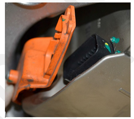
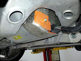
Disconnect the low voltage harness, then release the bolt and remove the orange
drive inverter cover (torque 3 Nm).
-
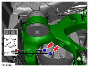
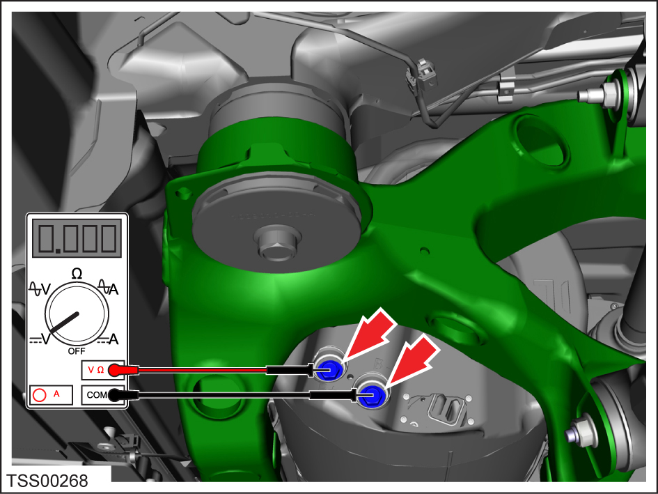
Use the drive inverter case as a chassis ground. Measure the following
voltages:
- B+ to ground
- B- to ground
- B+ to B-
 Warning: If any voltage reading is more than 10V, the high voltage contactors are not fully opened. Due to the risk of electrocution, contact Service Engineering before performing any further work.

Caution: To prevent future
water ingress, install new O-rings (1003784-00-A or later) on the drive inverter
cover and apply Silicone Lubricant (1010251-00-A) on both before installing the
cover. Insert the cover at an angle to prevent damage to the O-rings. Once the left
(B+) O-ring is seated, rotate the cover into position.