Mount - Front Drive Unit - RH (Remove and Replace)

FRT No: 39012402

Warning: If the 12V power supply is disconnected, do not attempt to open any doors with door glass in closed position. Failure to follow this instruction could result in door glass shatter.
Note: Before disconnecting the 12V power supply, ensure that the driver’s door window is fully open. Failure to follow this instruction could result in vehicle lockout.

Special tools required for this procedure:

Supplier Part Number Description
Tesla 1054160-00-A Support Jack, Front DU
Tesla 1056542-01-A Special 15 mm Ratchet Wrench
Tesla 1056566-00-A Locating Shim Set, Front drive unit

Removal

  1. Loosen the front RH wheel lug nuts (x5).
  2. Remove the HV battery (refer to procedure).
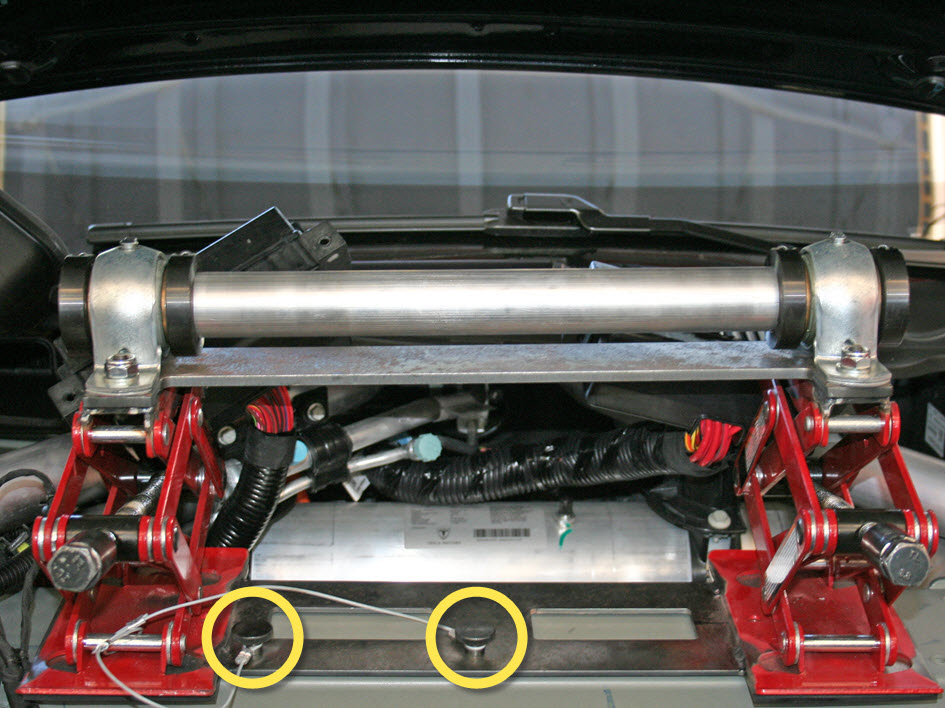
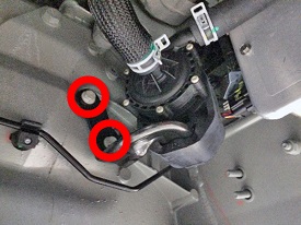
  3. Remove the bolts (x2) that secure the coolant pump bracket to the body of the vehicle.
  4. Disconnect the electrical connector from the battery coolant pump.
  5. Carefully secure the coolant pump away from the working area.
  6. Lower the vehicle.
  7. Remove the 12V battery bracket beam (refer to procedure).
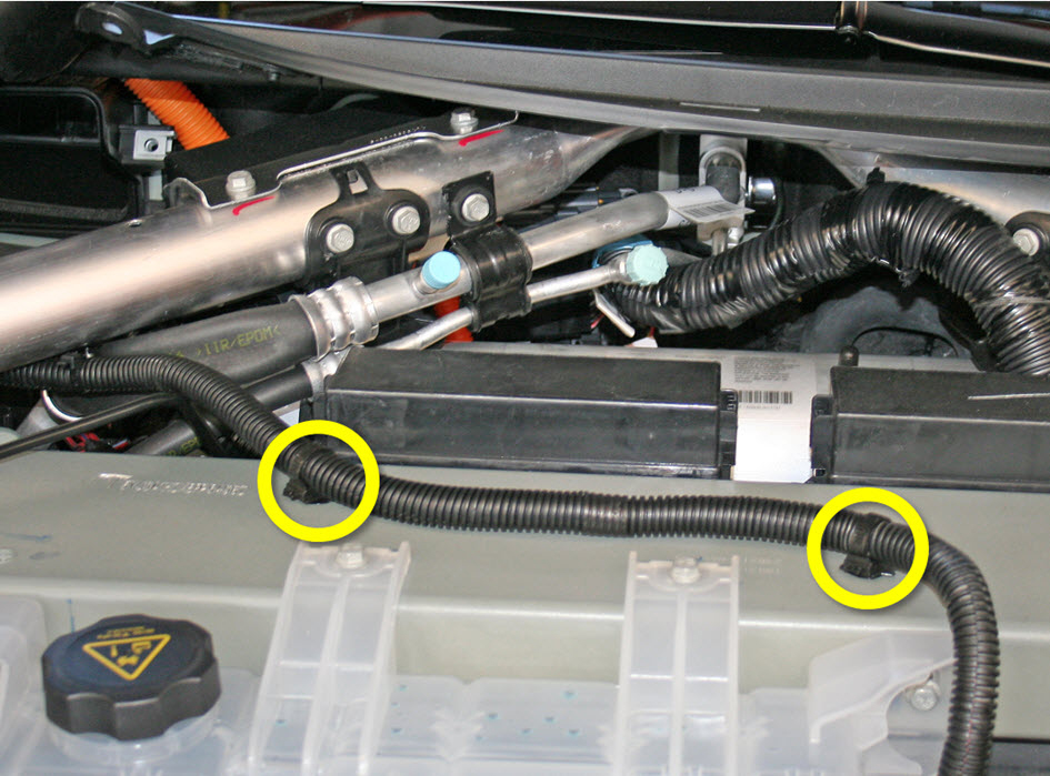
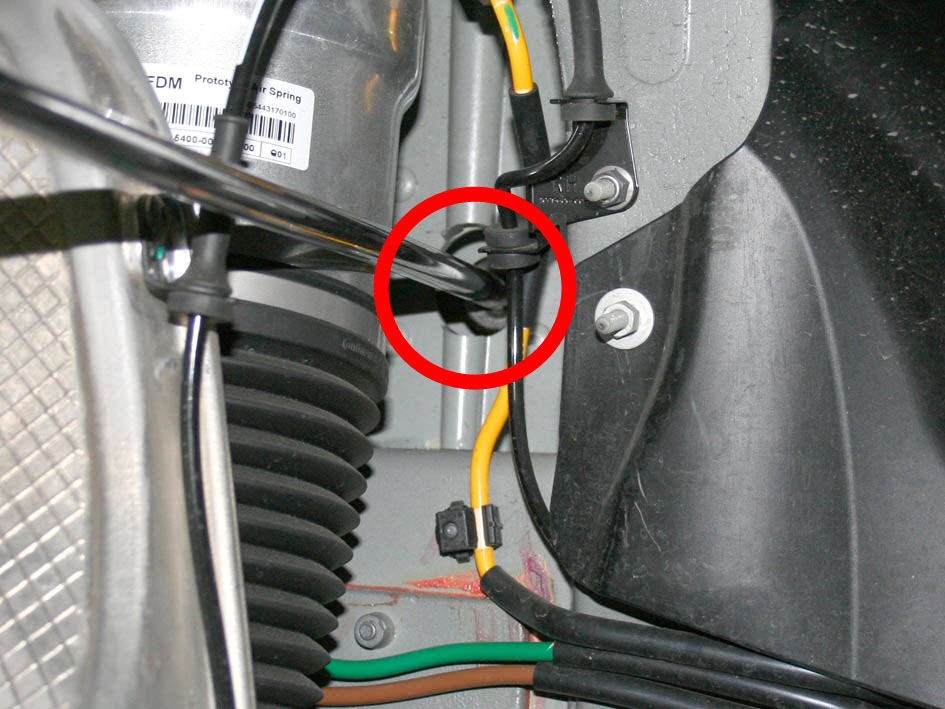
  8. Release the fir tree clips (x2) that secure the 12V positive harness to the front cross car beam.
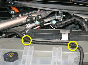
  9. Move the 12V positive harness to the RH side of the vehicle to keep it out of the working area.
  10. Release the bolts (x4) that secure the coolant reservoir to the cross car beam. Do not remove the reservoir at this time.
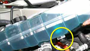
  11. Carefully lift up the coolant reservoir and disconnect the coolant level sensor harness.
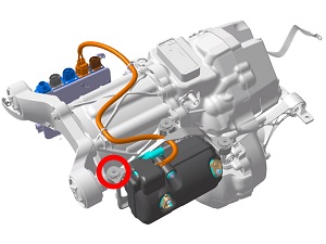
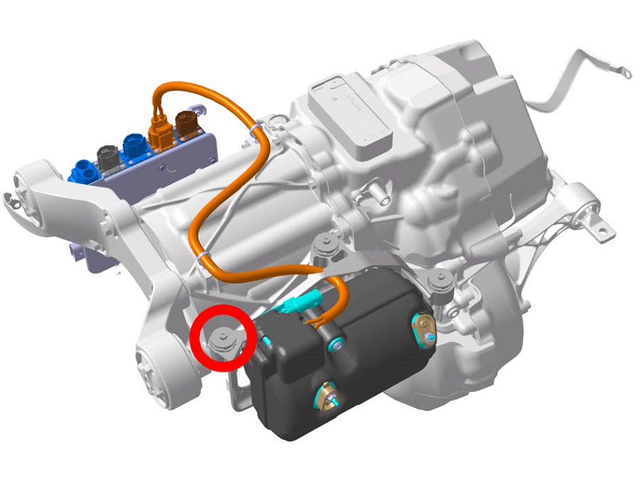
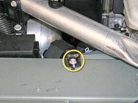
  12. Remove the RH bolt that secures the A/C compressor bracket to the front drive unit.
    Note: This allows the jack strap to slide between the front drive unit and the compressor.
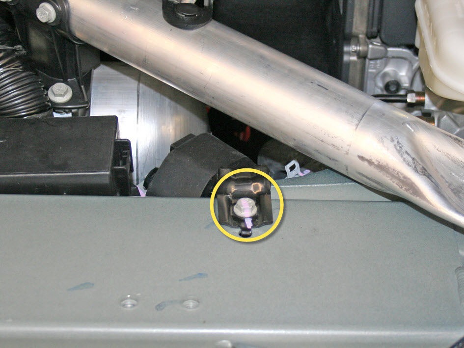
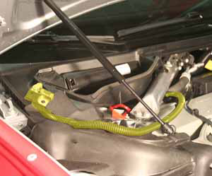
  13. Release the bolt that secures the coolant pump to the LH side of the front cross car beam.
  14. Remove the bolts (x4) that secure the front fuse boxes to the front shock tower crossmember. Move both fuse boxes behind the cross car beam.
  15. Position the support jack on top of the cross car beam and secure the screws (x2) to the cross car beam.
    Note: The support jack mounts to the bolt holes that secured the coolant reservoir.
  16. Fully lower both mounts of the support jack.
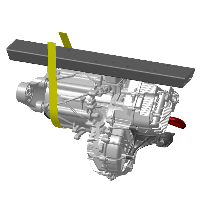
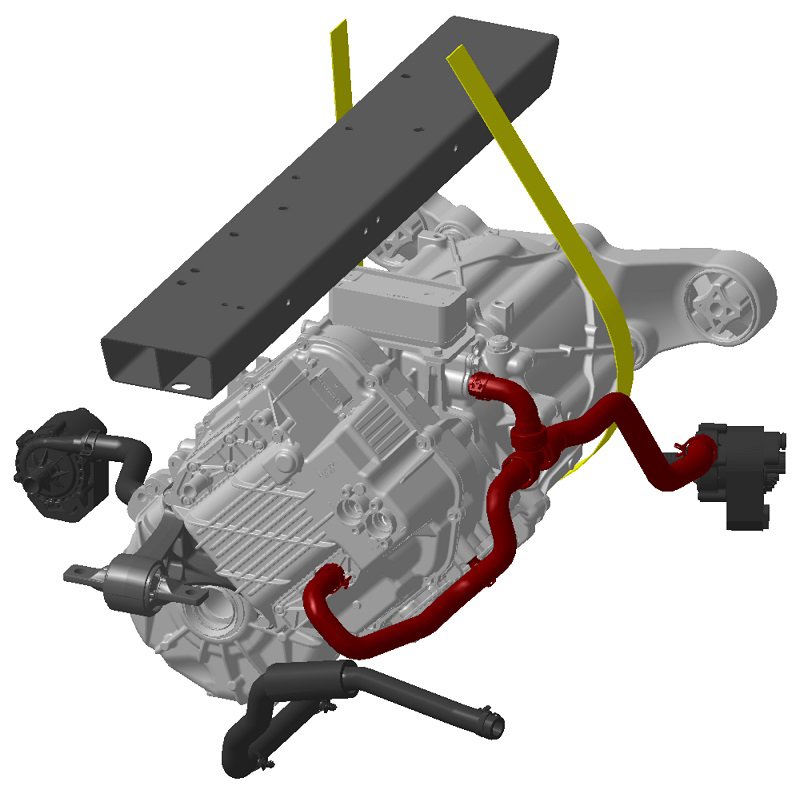
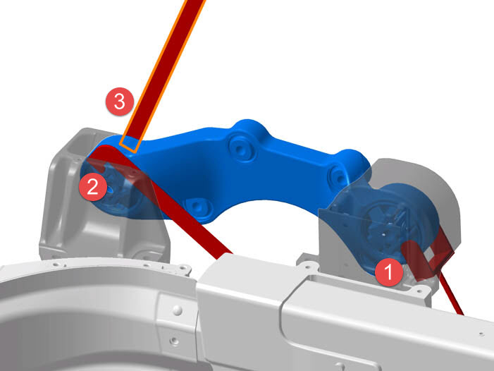
  17. Position the RH strap between the front drive unit and the A/C compressor:
    1. Lower one end of the strap over the top of the support jack and behind the front cross car beam.
    2. Reach beneath the drive unit and pull the strap upwards.
    3. Secure the two ends of the strap with the carabiner.
    4. Slide the strap so that the carabiner is approximately 6 inches (150 mm) above the front cross car beam.
  18. Raise both sides of the support jack alternately until the strap is fully taut.
    Caution: Even though only one strap is used in this procedure, it is important to raise both sides of the support jack.
  19. Raise the vehicle partially and remove the front RH wheel.
  20. Release the plastic rivets that secure the rear of the upper front arch liner, then pull the arch liner forward.
  21. Fully raise the vehicle.
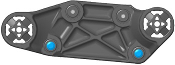
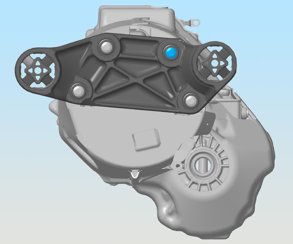
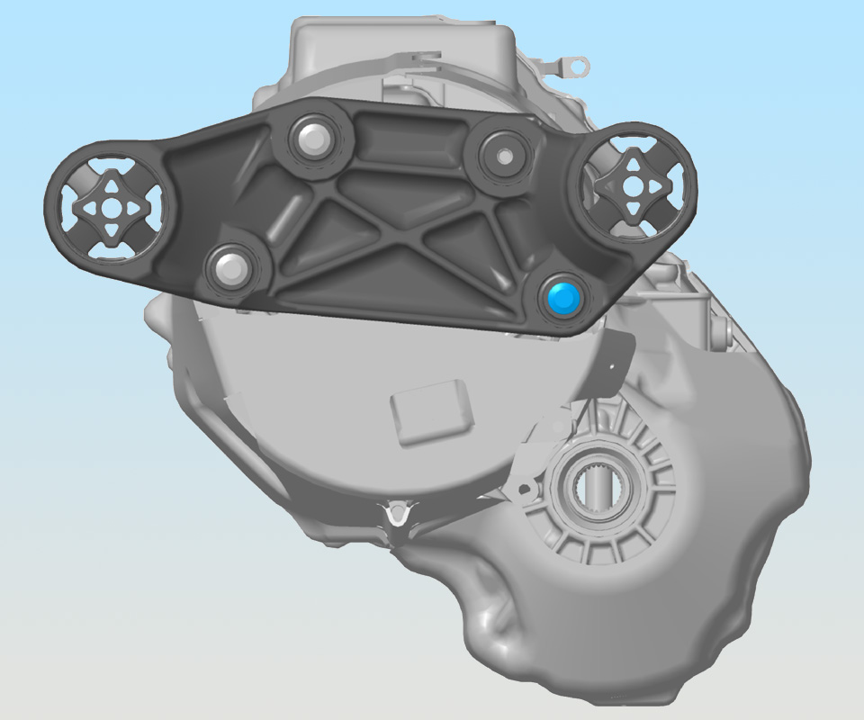
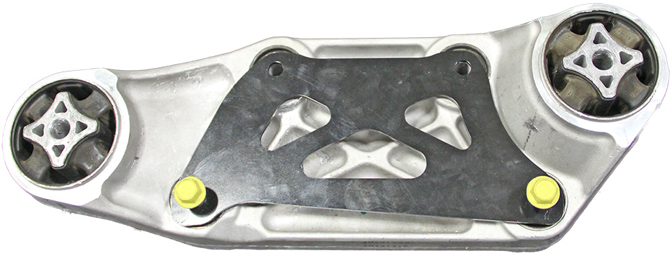
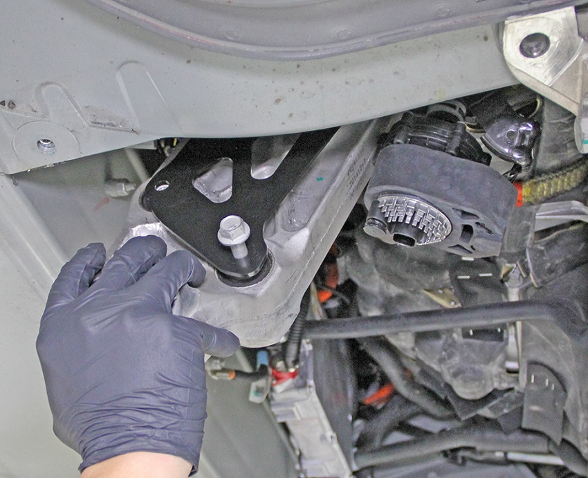
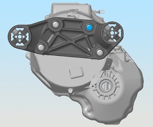
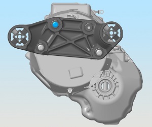
  22. Remove and discard the upper forward bolt that secures the mount to the drive unit.
  23. Release the lower forward bolt that secures the mount to the drive unit.
    Note: The lower bolt cannot be completely removed at this time.
  24. Lower the vehicle.
  25. Release the edge clip that secures the coolant pump hose to the body of the vehicle. Move the coolant hose away from the working area.
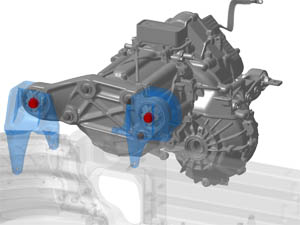
  26. Working from the RH wheelwell, use a socket wrench with an extension to remove the bolts (x2) that secure the mount to the body.
    1. Remove the rear bolt and washer.
    2. Remove the front bolt.
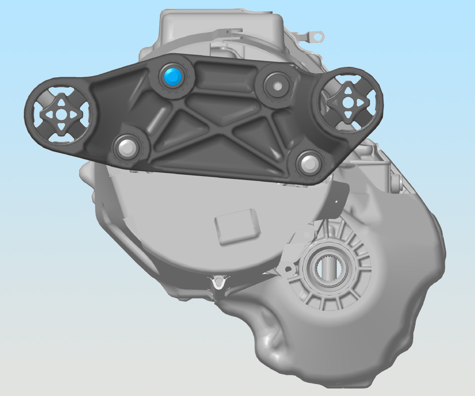
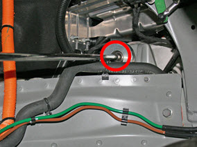
  27. Remove and discard the upper rear bolt that secures the mount to the drive unit.
  28. Release the lower rear bolt that secures the mount to the drive unit.
    Note: The lower bolts (x2) cannot be completely removed from the mount at this time.
  29. Raise the vehicle.
  30. Remove the RH drive unit mount.
    Note: Maneuver the mount between the coolant hoses during removal.
  31. Remove and discard the remaining lower bolts (x2) from the drive unit mount.
  32. If equipped, remove the shear plate from the drive unit mount.

Installation

  1. Use alcohol wipes to clean the mating surfaces between the RH drive unit mount and drive unit.
  2. Place a shear plate on the outboard side of the drive unit mount so that the shear plate bolt holes align with the motor mount bolt holes.
    Caution: Ensure that the bottom holes on the shear plate are not slotted. If the bottom holes are slotted, replace the shear plate with one that is not slotted.
    Note: Install a shear plate even if the original drive unit mount did not have a shear plate.
  3. Insert new bolts (x2) through the lower holes in the shear plate and motor mount.
  4. Set the new drive unit mount into position.
    Caution: Ensure that the bolts do not fall out from the drive unit mount while maneuvering the drive unit mount up to the front drive unit.
    Caution: Do not damage the RH axle during reinstallation.
    Note: The RH motor mount is reinstalled with the shear plate.
  5. Loosely install the lower bolts (x2) to the drive unit.
  6. Lower the vehicle.
  7. Alternate tightening the bolts on the support jack to raise the drive unit. Have an assistant monitor the installation from the RH wheelwell and underhood area to ensure that the bolt holes align correctly.
  8. Working from the RH wheelwell, hand tighten the bolts (x2) until they are snug; do not fully torque the bolts at this time.
    Tip: Install the forward bolt first. Have an assistant help align the rear bolt hole with the hole in the body.
  9. Align both lower bolts with the front drive unit. If equipped, install the torque reaction arm shear plate on the drive unit mount.
    Note: The lower holes (x2) on the torque reaction arm shear plate are slotted.
  10. Hand tighten both lower bolts.
    Note: The support jack might and/or drive unit might need to be slighlty adjusted when installing the lower bolts that secure the mount to the drive unit.
  11. Hand tighten the upper bolts (x2) that secure the mount to the drive unit.
  12. Position the 3 shim tools between the RH drive unit mount and body.
    Note: These tools ensure proper clearance. Leave them in place until prompted to remove, after all 6 bolts for the mount are fully torqued.
    1 2-pronged shim tool
    2 Hook shim tool
    3 Straight shim tool
    1. Working from the underhood area, position the 2-pronged shim around the RH drive unit mount front bushing.
    2. Reach beneath the drive unit and position the hook shim tool between the mount and outer bushing.
    3. Reach downward between the V-brace and cross brace and position the straight shim tool between the mount and inner bushing.
  13. Working from the RH wheelwell, fully torque the bolts that secure the mount to the body (torque 120 Nm).
  14. Raise the vehicle.
  15. Attach the 15 mm ratchet tool to a torque wrench.
    Caution: Ensure that the attachment is 90 degrees perpendicular to the torque wrench when using the tool.
    Note: Only use the ratcheting tool on the front 2 bolts.
    Tip: A Crowfoot wrench can be used in place of the ratchet tool.
    1 90 degree angle
  16. Fully torque the bolts (x4) that secure the drive unit to the mount in the order shown (torque 75 Nm).
  17. Lower the vehicle.
  18. Verify fitment of the alignment shims. Adjust as necessary.
  19. Remove the shim tools.
  20. Lower the support jack and release the strap from the drive unit.
  21. Release the screws (x2) that secure the support jack to the cross car beam. Remove the support jack from the vehicle.
  22. Install the bolts (x4) that secure the front fuse boxes to the front shock tower crossmember (torque 5 Nm).
  23. Install the bolt that secures the coolant pump to the front cross car beam (torque 6.5 Nm).
  24. Install the RH bolt that secures the A/C compressor bracket to the front drive unit (torque 10 Nm).
  25. Reconnect the coolant level sensor harness.
  26. Install the bolts (x4) that secure the coolant reservoir to the cross car beam (torque 6 Nm).
  27. Install the fir tree clips (x2) that secure the 12V positive harness to the front cross car beam.
  28. Install the 12V battery and bracket beam (refer to procedure).
    Caution: Do not connect the negative cable on the battery at this time.
  29. Raise the vehicle.
  30. Connect the battery coolant pump electrical connector.
  31. Install the bolts (x2) that secure the coolant pump bracket to the body of the vehicle.
  32. Install the HV battery (refer to procedure).
  33. Lower the vehicle partially.
  34. Install the edge clip that secures the coolant pump hose to the body of the vehicle.
  35. Reinstall the wheel arch liner.
  36. Reinstall the wheel.
  37. Lower the vehicle.
  38. Torque the lug nuts on the wheel (torque 175 Nm).
  39. Connect 12V power.
  40. Refill and bleed the cooling system (refer to procedure).
  41. Reinstall any remaining components that were removed for access.