Removal
Warning: Proper personal protective equipment (PPE) and insulating HV
gloves with a minimum rating of class 00 (500V) must be worn while performing the
remainder of this procedure.
Warning: Ensure that the multimeter and leads are capable of handling at
least 500V.
-
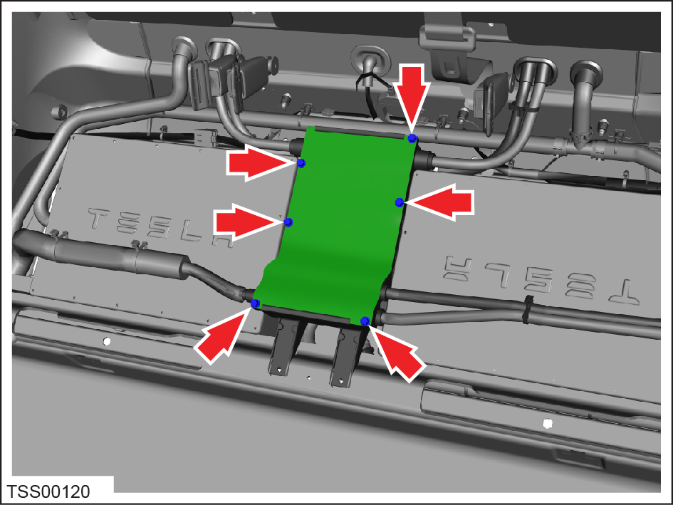
Remove the bolts (x6) that secure the HV junction box cover (torque 5 Nm).
Remove the cover.

-
Use a multimeter to check voltages across the HV cables and to ground:
- B+ to ground
- B- to ground
- B+ to B-Warning: If any voltage reading is more than 10V, the high voltage contactors are not fully opened. Due to the risk of electrocution, contact Service Engineering before performing any further work.
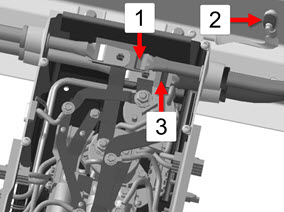
1 B+ 2 Ground 3 B-