HV Junction Box - 2nd Generation (Remove and Replace)

FRT No: 44301002

Warning: Only technicians who have been trained in High Voltage Awareness are permitted to perform this procedure. Proper personal protective equipment (PPE) and insulating HV gloves with a minimum rating of class 00 (500V) must be worn any time a high voltage cable is handled. Refer to Tech Note TN-15-92-003, "High Voltage Awareness Care Points" for additional safety information.

Removal

  1. Remove the high voltage junction box (HVJB) cover (refer to procedure).

Warning: Perform all of the voltage checks listed in the procedure. If any voltage reading is more than 10V, the high voltage contactors are not fully opened. Due to the risk of electrocution, contact Service Engineering before performing any further work.

  1. Release the 2 HVJB harness connections from the master charger by pressing on the tab on each connector. If the vehicle is equipped with dual chargers, repeat this step for the harness connections to the slave charger.
  2. Dual motor vehicles only: Mark the rear HV cable that leads to the front drive unit as B-, and the forward HV that leads to the front drive unit as B+.

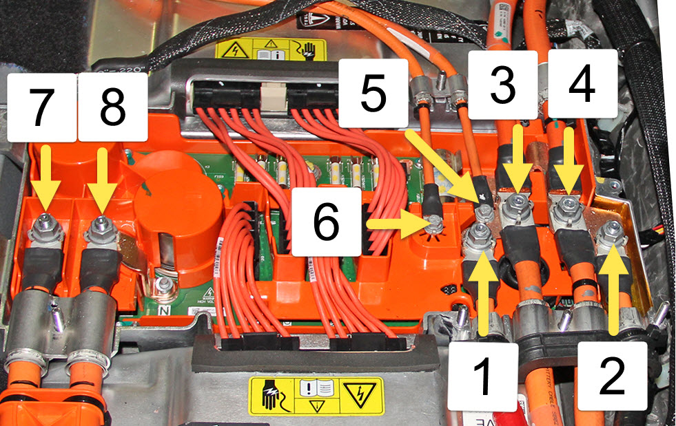
    Table 1: HV Cable fasteners inside HVJB

    1 B+ Front Drive Unit (if equipped)
    2 B- Front Drive Unit (if equipped)
    3 B+ battery/drive inverter
    4 B- battery/drive inverter
    5 B+ forward junction box
    6 B- forward junction box
    7 B- charge port
    8 B+ charge port
  3. Release the 2 nuts that secure the HV cables that lead to the front drive unit (torque 9 Nm).
    Note: Refer to Table 1.
    Note: It is not necessary to replace the fastener(s) after it is removed. The threaded area has a reusable dry sealant, which looks similar to adhesive patch material.
  4. Mark the rear HV cables that lead to the battery and drive inverter as B‒, and the forward HV cables that lead to the battery and drive inverter as B+.
    Note: Refer to Table 1.
  5. Release the 2 nuts that secure the HV cables that lead to the battery and drive inverter (torque 9 Nm).
    Note: Refer to Table 1.
    Note: It is not necessary to replace the fastener(s) after it is removed. The threaded area has a reusable dry sealant, which looks similar to adhesive patch material.
  6. Mark the rear HV cable that leads to the forward junction box as B+ and the forward HV cable that leads to the forward junction box as B-.
    Note: Refer to Table 1.
  7. Release the 2 bolts that secure the HV cables that lead to the forward junction box (torque 4 Nm).
    Note: It is not necessary to replace the fastener(s) after it is removed. The threaded area has a reusable dry sealant, which looks similar to adhesive patch material.
  8. Mark the HV cables that lead to the charge port.
    • Single-phase charging: Mark the forward cable as B- and the rear cable as B+.
    • 3-phase charging: Starting from the front and working toward the rear of the vehicle, mark the 4 HV cables that lead to the charge port from front to rear as L2, L3, L1, and N.
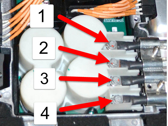
    Note: Vehicles equipped with 3-phase charging have 4 charge port cables instead of 2.

    Table 2: 3-Phase charge port cables

    1 B+ N charge port
    2 B- L1 charge port
    3 B+ L3 charge port
    4 B- L2 charge port
  9. Release the bolts that secure the HV cables that lead to the charge port.
    • North America, Japan: 2 bolts (torque 9 Nm).
    • Europe, APAC: 4 bolts (torque 4 Nm).
    Note: Refer to Table 1.
    Note: It is not necessary to replace the fastener(s) after it is removed. The threaded area has a reusable dry sealant, which looks similar to adhesive patch material.
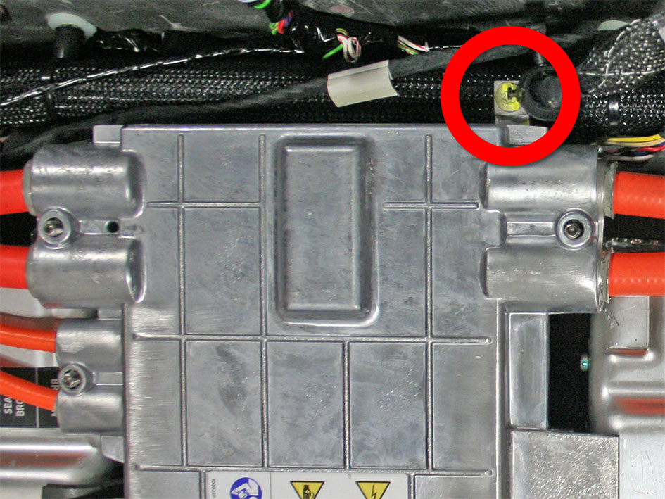
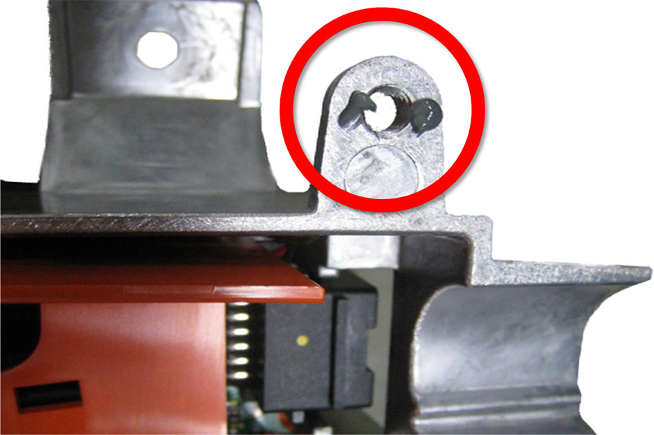
  10. Release the bolt that secures the ground strap to the rear of the HVJB (torque 6 Nm).
    Note: Leave the ground strap secured to the vehicle.
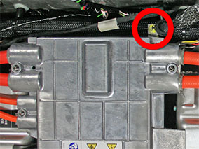
  11. Disconnect the low voltage harness connection on the rear LH side of the HVJB .
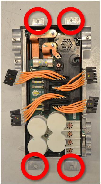
  12. Release the 4 bolts that secure the HVJB to the body (torque 5 Nm). Remove the HVJB from the vehicle.

Installation

Installation procedure is the reverse of removal, except for the following: