Forward Junction Box (Dual Motor) (Remove and Replace)

FRT No: 44200602

Warning: Only technicians who have been trained in High Voltage Awareness are permitted to perform this procedure. Proper personal protective equipment (PPE) and insulating HV gloves with a minimum rating of class 00 (500V) must be worn any time a high voltage cable is handled. Refer to Tech Note TN-15-92-003, "High Voltage Awareness Care Points" for additional safety information.

Removal

  1. Disconnect 12V and HV power (refer to procedure).
  2. Remove the wiper motor (refer to procedure).
  3. Remove the LH and RH shock tower to bulkhead struts (refer to procedure).
  4. Release the 2 bolts that secure each fuse box to the front crossmember (torque 5 Nm).
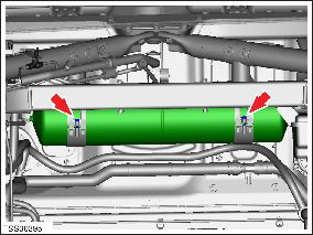
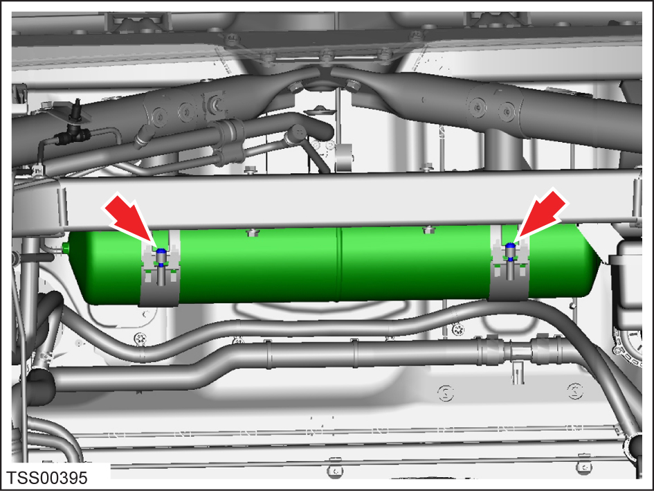
  5. If the vehicle is equipped with air suspension, release the bolts (x2) that secure the air reservoir (torque 2.5 Nm). Carefully set the reservoir in the RH side of the underhood area.
    Note: It is not necessary to disconnect the air lines.
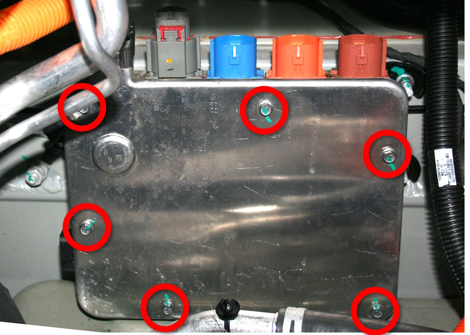
  6. Release the bolts (x6) that secure the forward junction box cover (FJB) (torque 6.5 Nm). Remove the cover.

Warning: Before continuing, put on high voltage gloves.

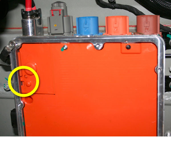
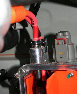
  1. Use a small, insulated screwdriver or similar tool to pry open the cover on the front upper left of the FJB.
    Warning: Do not use a metallic tool to open the cover.
  2. Use a multimeter to check voltages between:
    • B+ to ground
    • B- to ground
    • B+ and B-
    Warning: If any voltage reading is more than 10V, the contactors are not fully opened. Discontinue this procedure immediately. Contact a Field Service Engineer before performing any further work.
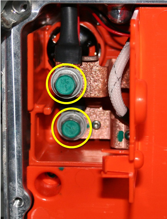
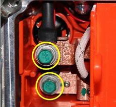
  3. Release the bolts (x2) that secure the HV cables to the busbars inside the FJB (torque 4 Nm).
  4. Release the 4 harnesses from the top of the FJB.
    1 HV Battery heater harness
    2 DC-DC converter harness
    3 Compressor harness
    4 PTC heater harness
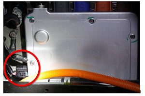
  5. Release the 12V harness from the RH side of the FJB.
  6. Release the clips (x2) that secure the HV cables.
    Note: The O-rings on the HV cables might create suction, which makes the cables difficult to remove. It might require greater than normal force to release the cables.
  7. Release the bolts (x3) that secure the FJB to the body (torque 10 Nm). Carefully remove the FJB.

Installation

Installation procedure is the reverse of removal, except for the following:

If necessary, adjust the wipers (refer to procedure).