HV Harness - Rapid Splitter to FJB (Remove and Replace)

FRT No: 44503202

Warning: Only technicians who have been trained in High Voltage Awareness are permitted to perform this procedure. Proper personal protective equipment (PPE) and insulating HV gloves with a minimum rating of class 00 (500V) must be worn any time a high voltage cable is handled. Refer to Tech Note TN-15-92-003, "High Voltage Awareness Care Points" for additional safety information.

Special tools required for this procedure:

Note: The following tools are included in the rapid splitter tool kit (Tesla Part Number: 1073594-00-A).
Supplier Part Number Description
Tesla 1064832-01-A SOCKET, RAPID SPLITTER, MDLX
Tesla 1072083-00-A SEAL INSTALLATION TOOL
Tesla 1072084-00-A INSTALLATION TOOL, RAPID SPLITTER
Martin Tools BC32 1” FLARE NUT CROW FOOT WRENCH, 3/8” DRIVE
Tesla 10794924-00-A Nylon Fish Tape, 25 ft.

Removal

  1. Remove the rear subframe (refer to procedure).
  2. Remove the HV battery (refer to procedure).
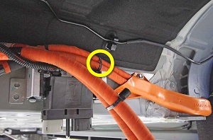
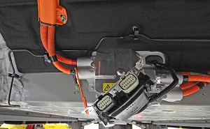
  3. Remove the barrel clip that secures the HV cables to the body of the vehicle.
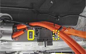
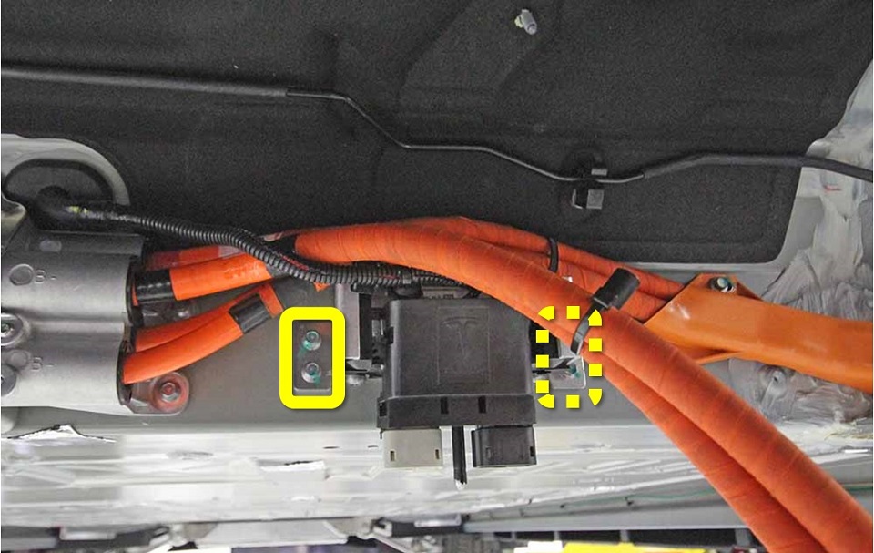
  4. Remove the bolts (x4) that secure the low voltage (LV) Rapid Mate bracket to the body of the vehicle (torque 8 Nm).
    Note: These bolts are self-tapping and can strip the threads in the body. Before reinstalling, ensure that the female threads are not stripped. If they are, install a rivnut.
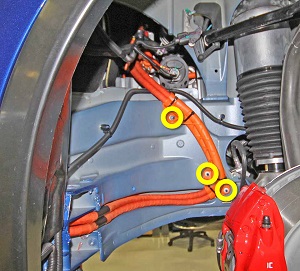
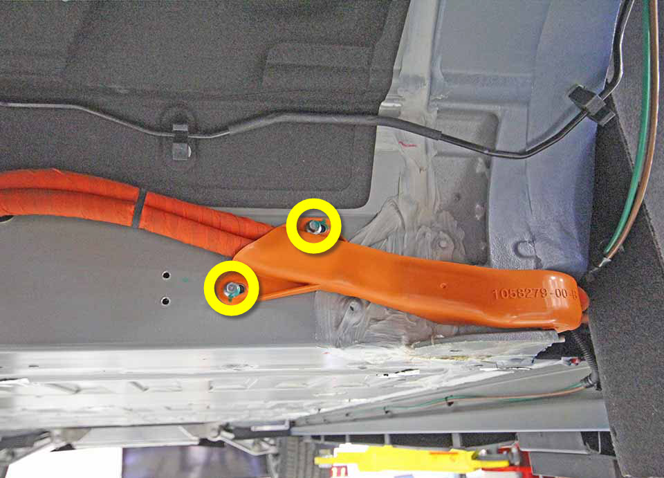
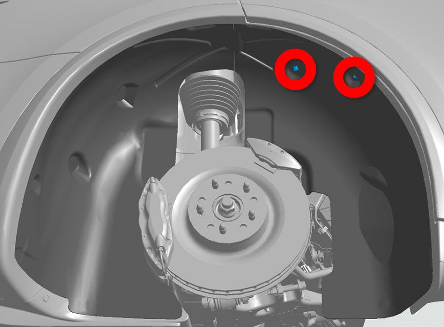
  5. Remove and discard the bolts (x2) that secure the HV cable bracket to the body of the vehicle (torque 8.3 Nm).
  6. Release the LV Rapid Mate and secure it out of the working area.
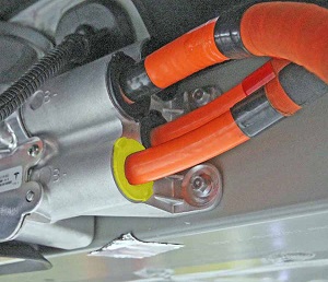
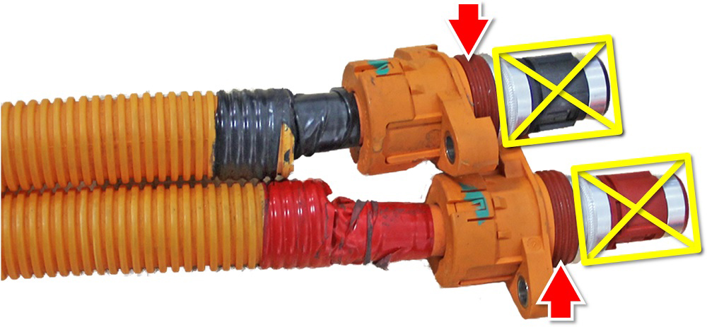
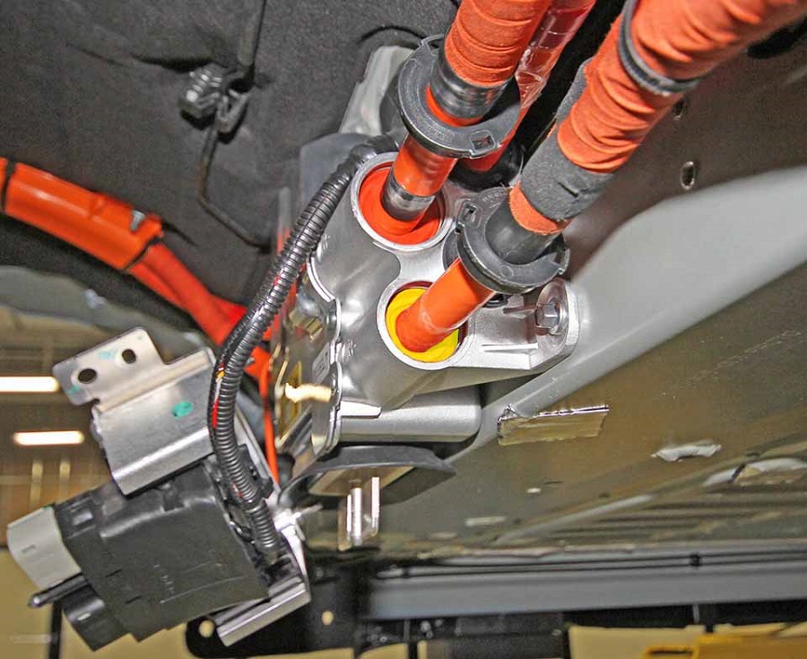
  7. Remove the B- HV cable from the Rapid Splitter:
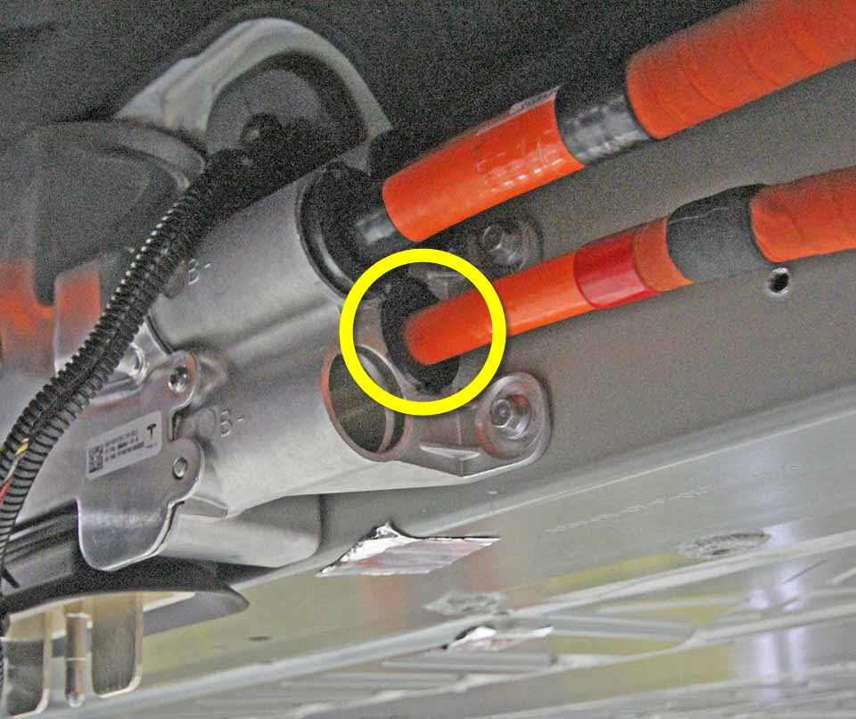
    1. Use a screwdriver or pick to release the black retaining collar from the Rapid Splitter. Slide the retaining collar down the HV cable, away from the Rapid Splitter.
    2. Use a pick to release the O-ring from the Rapid Splitter.
    3. Carefully cut through the O-ring and remove it from the HV cable.
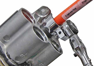
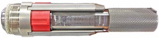
    4. Insert the rapid splitter socket into the B- cavity and twist it until the tool until it is lined up with the locking collar tabs.
      Note: If the tape on the HV cable prevents the retaining collar from moving enough to allow access for the special tool, remove it.
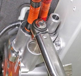
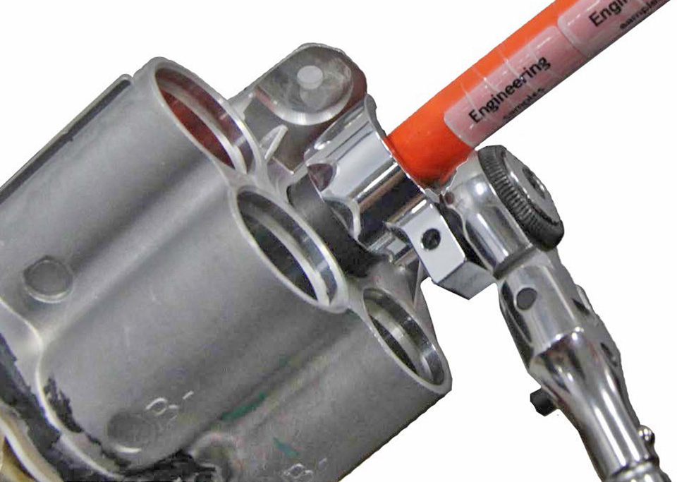
    5. Use the flare nut crowfoot wrench to rotate the socket, removing the cable holder threads from the Rapid Splitter.
      Note: The following image shows the wrench removing the B+ cable.
    6. Carefully remove the spring from the end of the HV cable.
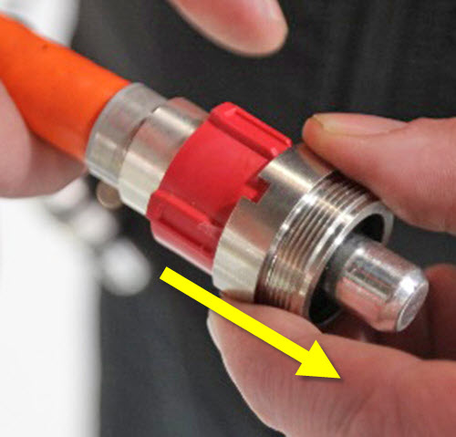
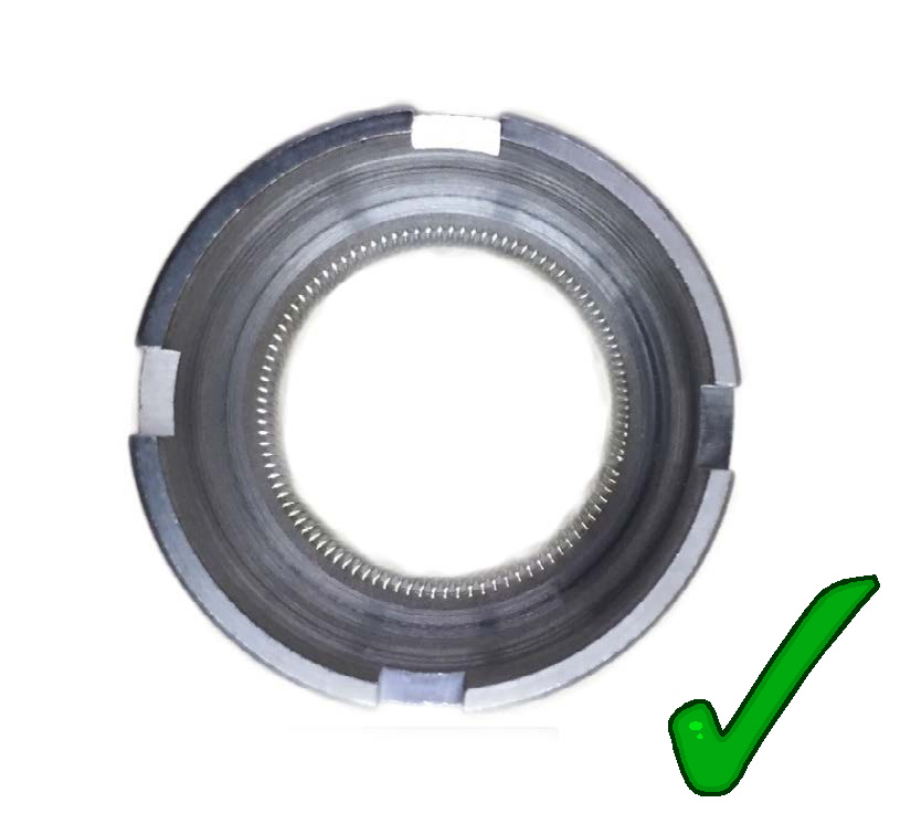
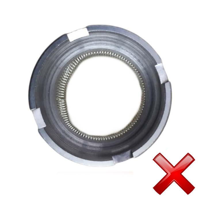
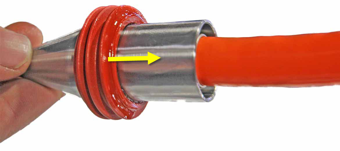
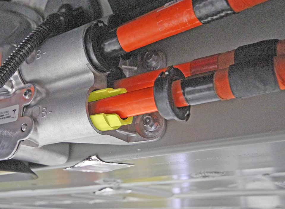
    7. While holding the metal piece in place, twist the plastic cap until the tabs and grooves are aligned. Once the tabs and grooves are aligned, the collar can be removed from the HV cable.
      Twist plastic cap Tabs highlighted Remove collar
    8. Inspect the plastic cap for damage. Replace if damaged.
    9. Discard the retaining spring.
      Note: The retaining spring is a one-time use part. Do not reuse the retaining spring.
    10. Place an HV cover on the end of the HV cable.
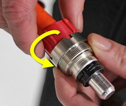
  8. Repeat the previous step on the B+ HV cable.
    Tip: Remove the cable tie that holds the HV cables together. Move the B- HV cable out of the working area for more access to the B+ HV cable.
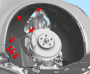
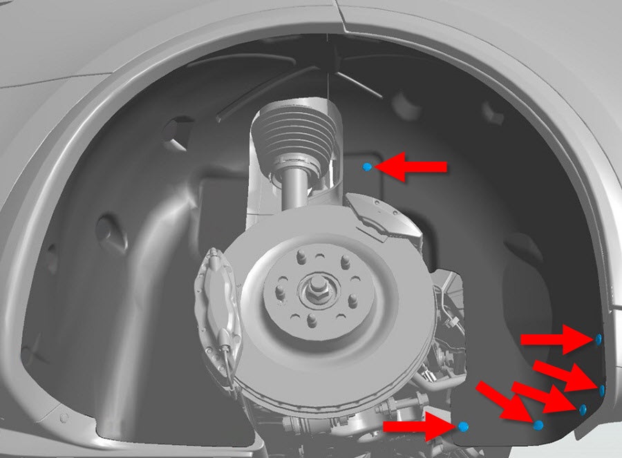
  9. Release the forward push clips (x6) that secure the RH rear wheel arch liner to the vehicle.
  10. Remove the forward nuts (x2) that secure the wheel arch liner to the studs on the chassis (torque 6 Nm).
  11. Move the rear wheel arch liner for access.
  12. Release the edge clips (x2) that secure the HV cable to the body of the vehicle.
  13. Remove the RH front wheel (refer to procedure).
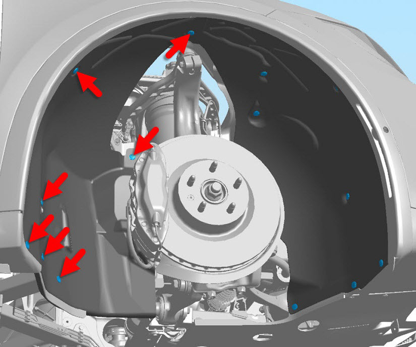
  14. Release the rear push clips (x7) that secure the front wheel arch liner to the vehicle.
  15. Remove the rear nut that secures the front wheel arch liner to the stud on the chassis (torque 6 Nm).
  16. Move the front wheel arch liner for access.
  17. If equipped, remove the bolts (x4) that secure the side sill closing panel to the wheel well (torque 25 Nm).
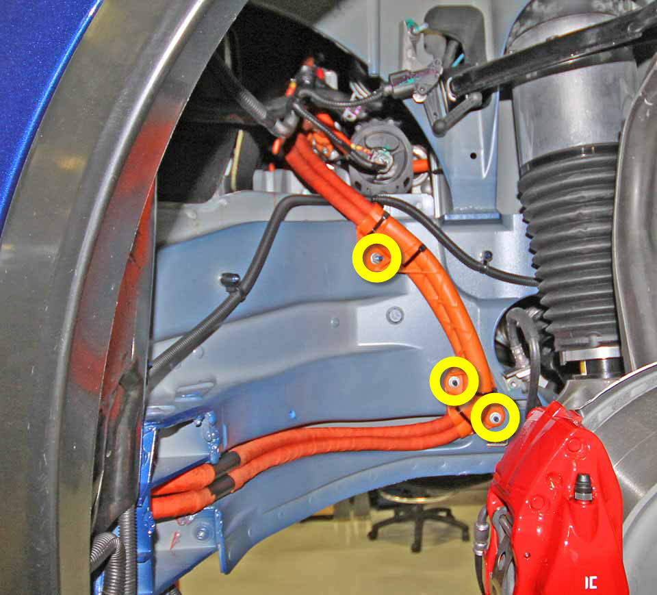
  18. Remove the nuts (x3) that secure the HV cable bracket to the studs on the body of the vehicle (torque 4 Nm).
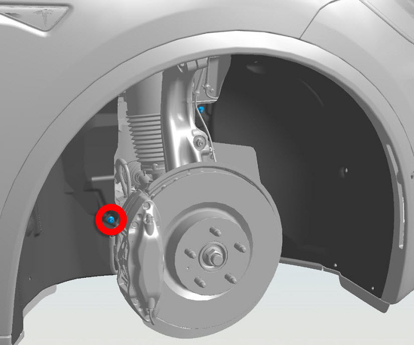
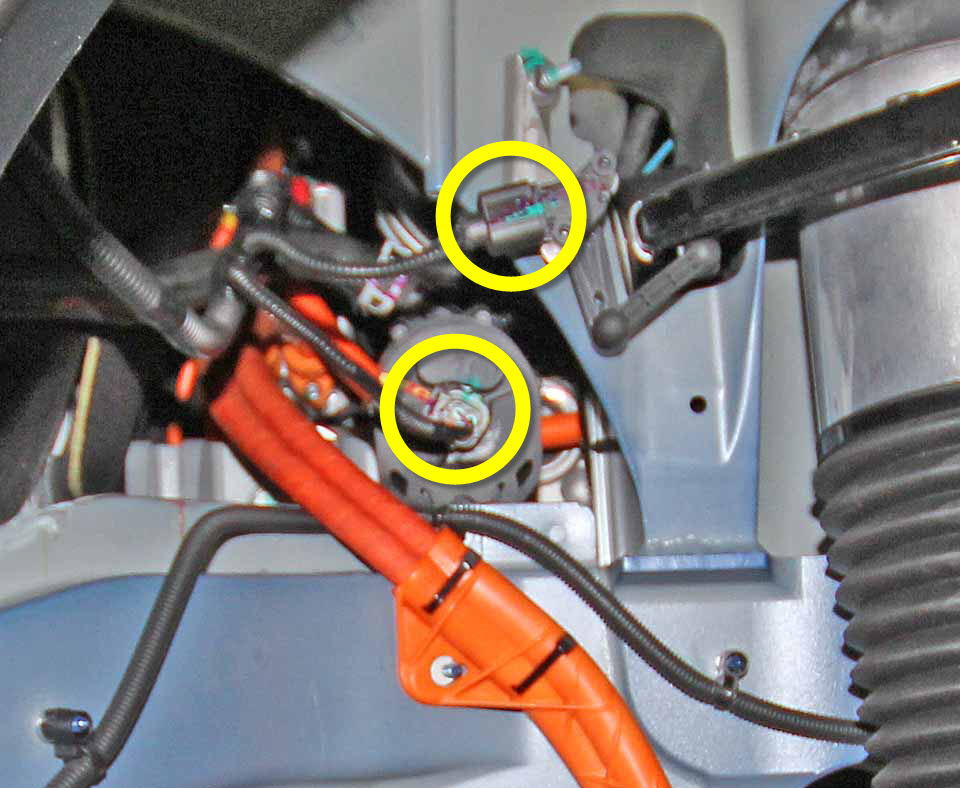
  19. Disconnect the electrical connector from the following:
    • Powertrain coolant pump 1
    • Suspension level sensor
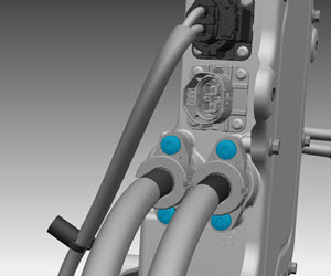
  20. Working from the wheel well, use an extension to release the screws (x4) that secure the HV cables to the forward junction box (FJB) (torque 7 Nm).
    Note: Components have been removed in this graphic to aid clarity.
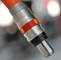
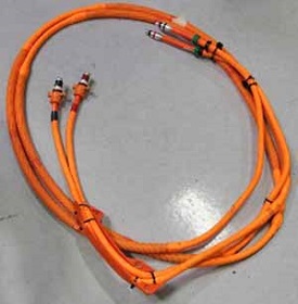
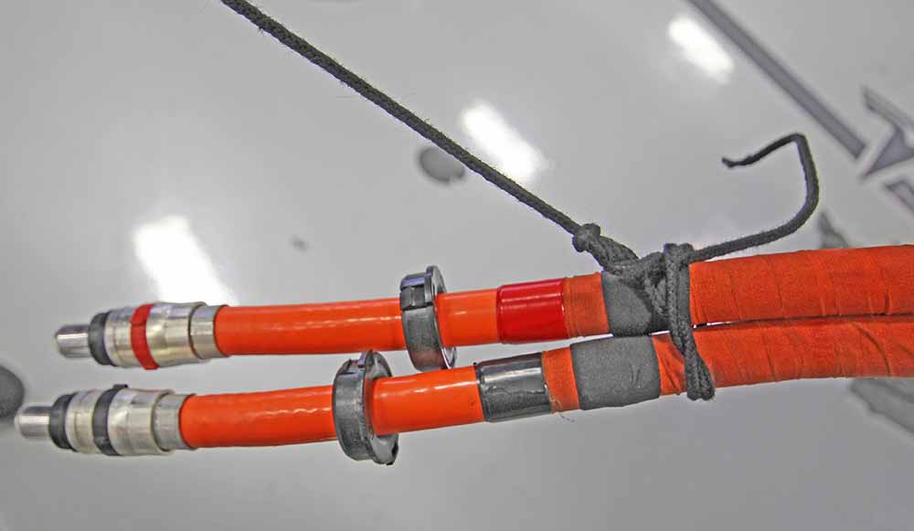
  21. Working from the rear RH wheel well, secure the HV cables to the nylon fish tape tool using string or fishing line.
    Note: The nylon fish tape tool is used to pull and route the new harness through the channel during installation.
    Note: Secure both HV cables together and slightly staggered to reduce the likelihood of one of them getting caught in the channel.
    Note: The following image shows the HV cables without the protective caps installed.
  22. Gently pull the HV harness towards the front of the vehicle and through the channel.
    Caution: Ensure that the string or fishing line is not accidently released from the HV cables while pulling them through the channel.
  23. Once the HV cables are all the way through the channel, release the string or fishing line from the cables, but do not pull the nylon fish tape tool back through the channel or remove it from the vehicle.
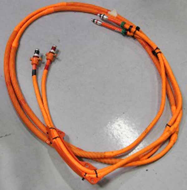
  24. Remove the HV cables from the vehicle.

Installation

Installation procedure is the reverse of removal, except for the following:

Caution: Replace all Patchbolt(s).
  1. Install protective caps over both HV cables to protect the terminals and seals when pulling the harness through the channel.
  2. Secure the new HV harness to the nylon fish tape tool using string or fishing line and, from the rear RH wheel arch, gently pull the front of the nylon fish tape tool through the channel towards the rear of the vehicle and retrieve the HV harness.
  3. Apply P-80 emulsion to the connector seals on the HV cables before securing the HV cables to the FJB.
    Caution: Do not apply P-80 emulsion to the HV terminals.
  4. Inspect the retaining springs before installing the locking collars. Ensure that the retaining spring is seated correctly.
    Retaining spring seated correctly Retaining spring seated incorrectly Retaining spring seated incorrectly
  5. Use the installation tool to install both locking collars in the Rapid splitter.
    Note: Install both locking collars into the Rapid Mate before installing either of the HV cables.
  6. Use the flare nut crowfoot wrench at 90 degrees from the torque wrench when torquing the collar (torque 35 Nm).
    Caution: If the flare nut crowfoot wrench is not 90 degrees from the torque wrench, it can damage the special tool and/or the rapid splitter.
  7. After inserting the new HV cables into the Rapid Splitter, perform pull test to ensure that the cables are correctly installed.
    Note: The HV cables must be pulled with a force of 150N.
  8. Install the O-rings on the HV cables:
    1. Place the seal installation tool over the terminal.
    2. Apply P-80 emulsion to the seal installation tool.
    3. Push the O-ring along the seal installation tool until it slides onto the HV cable.
    4. Remove the seal installation tool from the HV cable.
    5. Perform steps a-d on the other HV cable.