Front Drive Unit (From Above) (Remove and Install)

FRT No: 39012001

Note: If possible, use the "From Below" procedure to remove and install the front drive unit (refer to procedure).

Special tools required for this procedure:

Supplier Part Number Description
Tesla 1054160-00-A Support Jack, Front DU
Tesla 1056360-00-A Service Cover, Steering Rackg
Tesla 1054946-00-A Fluid Transfer Pan
Tesla 1056542-01-A Special 15mm Ratchet Wrench
Tesla 1056566-00-A Locating Shim Set, Front Motor
Bosch 682-Q3MEC2T 2 Ton Foldable Engine Crane
Tesla 1056361-00-A Oberg Tilt-Lift
Tesla 1057312-00-A Axle Extractor
Tesla 1051629-00-A Cap, Connection, Rosenberger, H4Z001-000/52

Remove Components For Access

  1. Remove the front wheels (refer to procedure).
  2. Release the fasteners that secure the lower arch liners. Fold the arch liner forward to access the rear of the wheelwell.
  3. Lower the vehicle.
  4. Remove the 12V battery bracket beam (refer to procedure).
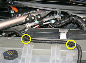
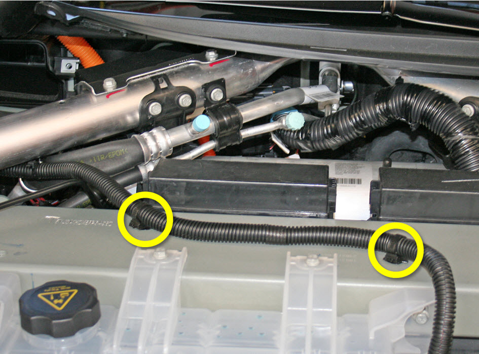
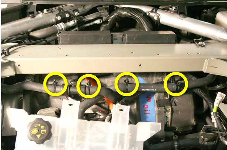
  5. Release the 2 fir tree clips that secure the 12V positive harness to the front crossmember.
  6. Move the 12V positive harness to the RH side of the vehicle to keep it out of the working area.
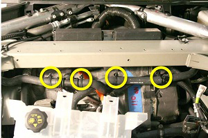
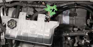
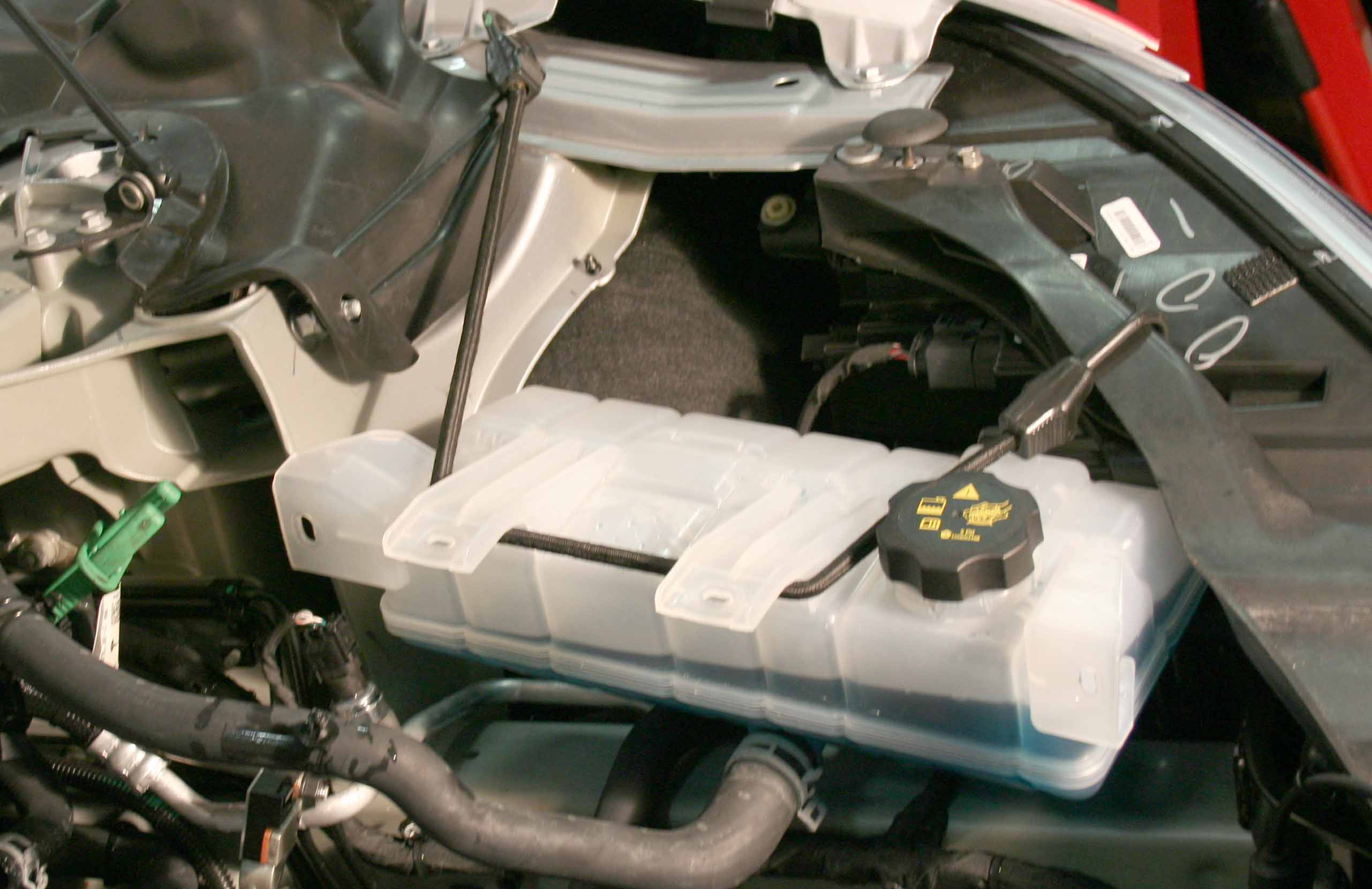
  7. Release the 4 bolts that secure the coolant reservoir to the front crossmember (torque 6 Nm). Do not remove the reservoir at this time.

Caution: At this point in the procedure, there are still 2 coolant hoses and 1 harness attached to the reservoir.

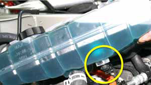
  1. Carefully lift up the coolant reservoir and disconnect the coolant level sensor harness.
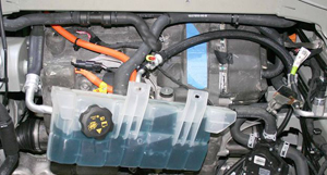
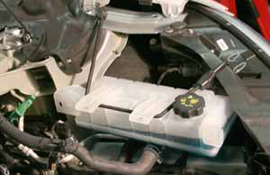
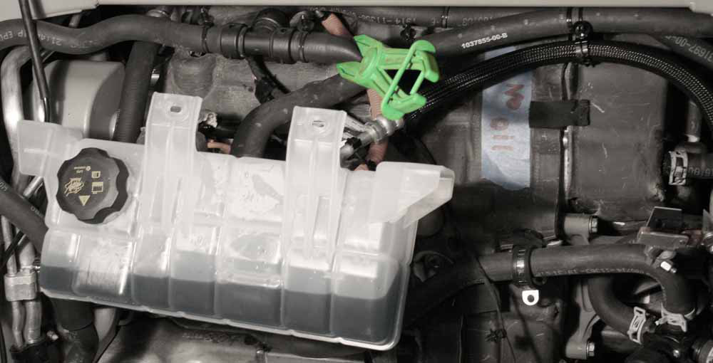
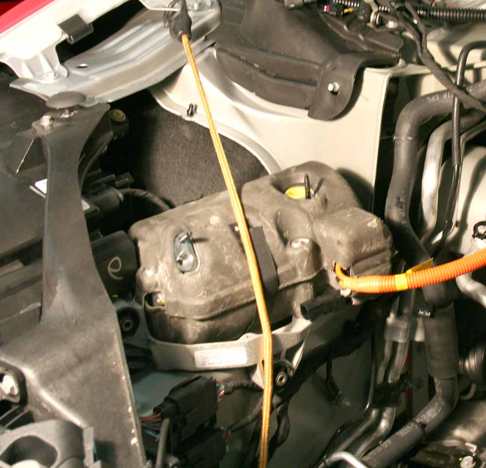
  2. Ensure that the cap on the reservoir is properly secured, then pull the reservoir forward into the underhood area.
    Note: The reservoir hose is routed behind the drive unit hose. Note the routing of the hoses and ensure that they are routed correctly during reinstallation.
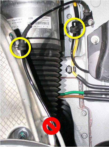
  3. Gently pull down on the 2 coolant hoses to release the clips (x4) that secure them to the front crossmember.
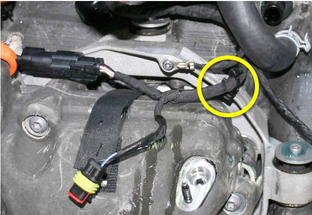
  4. Release the clip that secures the coolant reservoir hose to the A/C line.
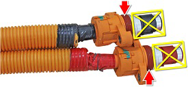
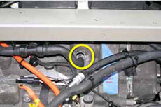
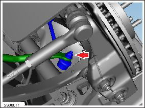
  5. On the LH side of the 3-way fitting, clamp the coolant hose that leads to the differential housing. Remove the hose from the front drive unit and and plug the nipple.
  6. Move the coolant reservoir to the LH side of the vehicle and secure it out of the working area.
    Caution: The reservoir is still secured to 2 coolant hoses.
  7. On the LH side of the drive unit, clamp the coolant hose. Remove the hose and plug the nipple.
    Tip: Use flexible hose clamp pliers to release the locking ring.
  8. Move the clamped drive unit coolant hose to the RH side of the vehicle so that it is out of the working area.
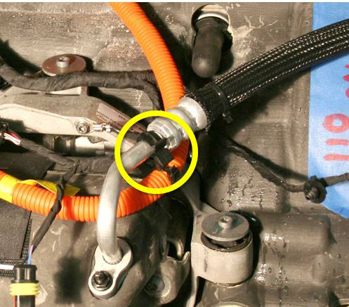
  9. Release the clip that secures the LH A/C line to the compressor HV harness.
  10. Release the 2 nuts that secure the A/C lines to the compressor. Plug both holes and cap both lines.
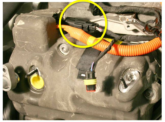
  11. Disconnect the compressor LV harness.
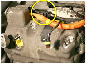
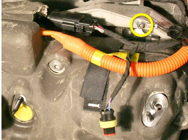
  12. Release the ground strap from the A/C compressor bracket (torque 7 Nm).
  13. Release the edge clip that secures the LV harnesses to the compressor bracket.
  14. Release the fir tree clip that secures the LV harnesses to the top of the front drive unit.
  15. Wrap the LV harnesses around the RH hood strut so that they are out of the working area.
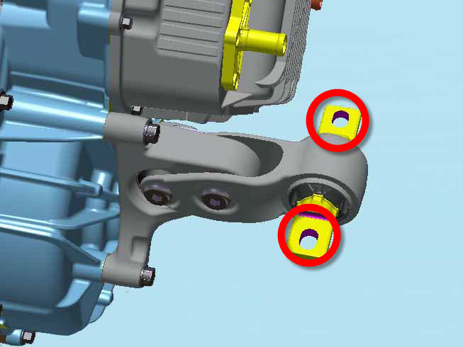
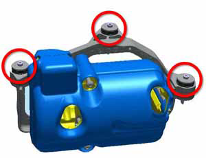
  16. Have an assistant support the compressor. Release the 3 bolts that secure the A/C compressor bracket to the front drive unit (torque 10 Nm).
    Caution: Do not spill any oil when removing the compressor.
  17. Move the compressor and bracket to the RH side of the vehicle and secure them outside of the working area.
  18. Raise the vehicle.

Note: Perform the next 3 steps on both sides of the vehicle.

  1. Release the nut that secures the sway bar end links to the sway bar (torque 70 Nm).
  2. Release the wheel speed sensor harness from the brackets on the knuckle and the body.
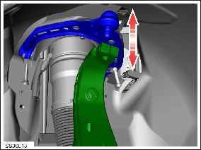
  3. Release the bolt that secures the upper control arm to the knuckle (torque 60 Nm).
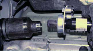
  4. Temporarily lower the vehicle and remove the RH halfshaft from the jackshaft.
    Tip: Use a deadblow hammer to separate the halfshaft.
  5. Raise the vehicle to access the RH wheelwell.
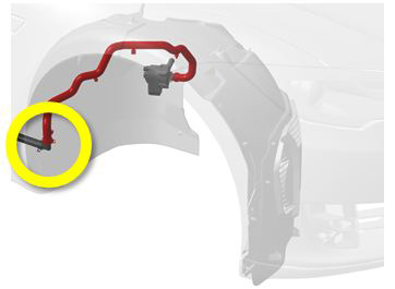
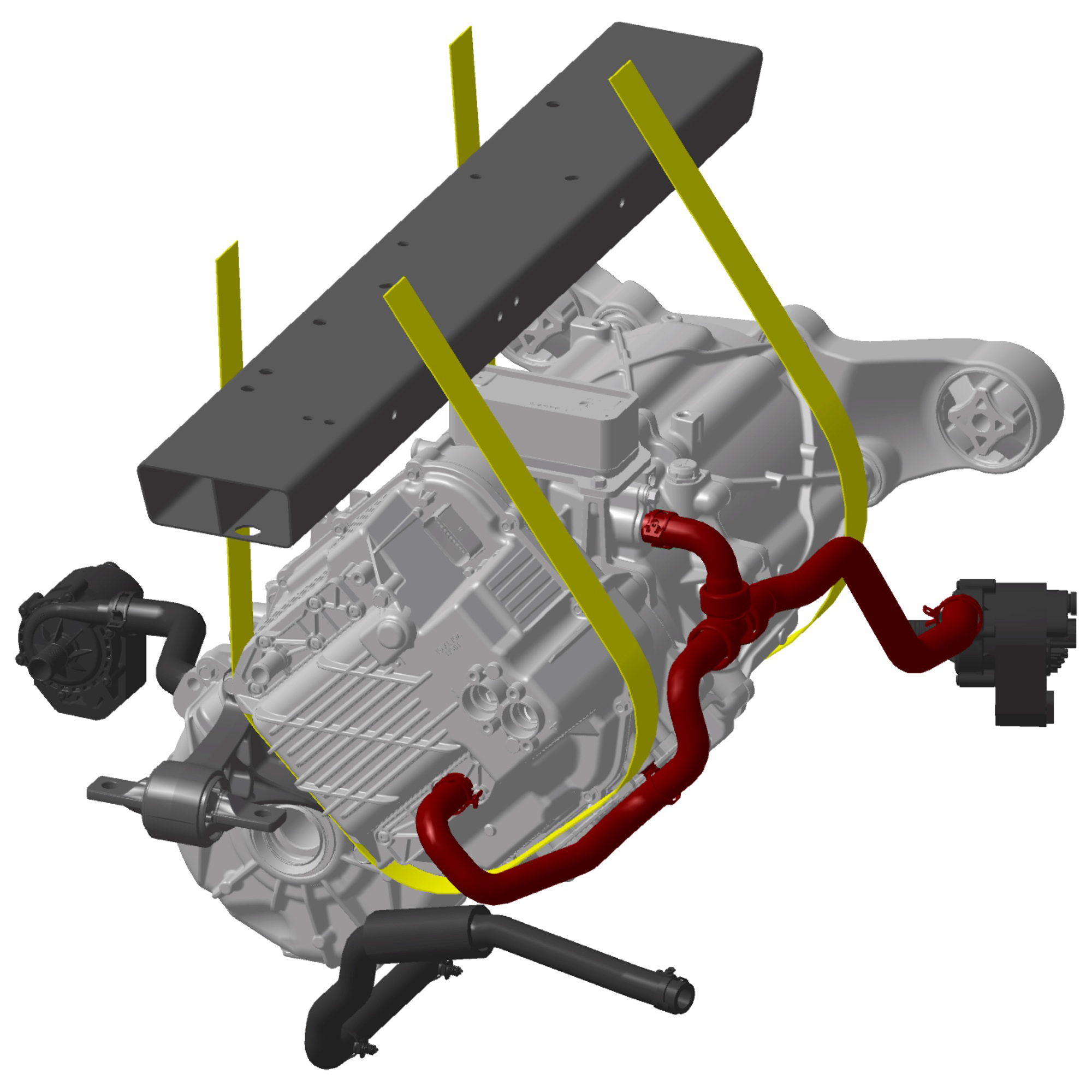
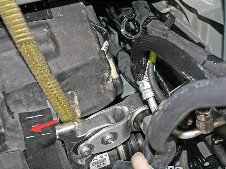
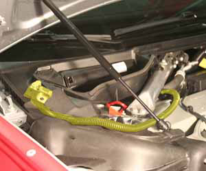
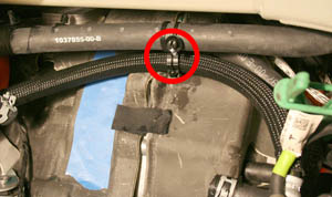
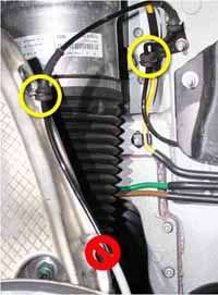
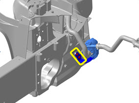
  6. At the rear base of the RH wheelwell, release and drain the coolant hose that leads to coolant pump 4.
    Note: This is necessary because the coolant hose and pump are removed with the drive unit.

    Hose highlighted in red

  7. Release any clips that secure the coolant hose to the body.
  8. Lower the vehicle to provide easier access to the underhood area.
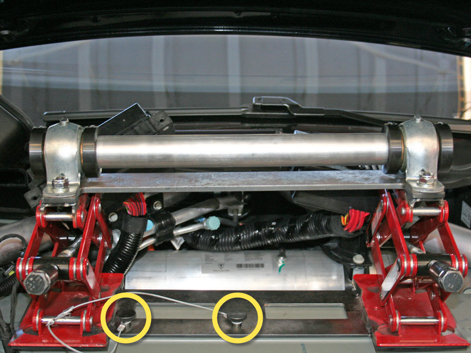
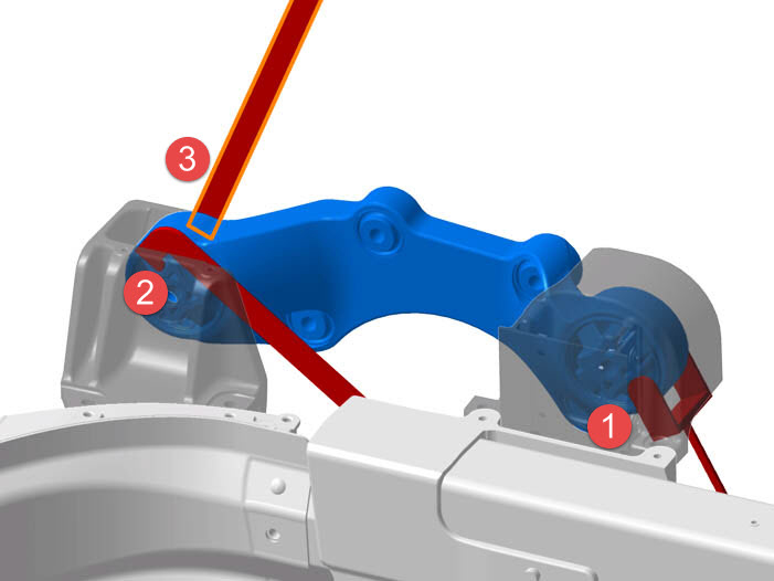
  9. Working from the underhood area, release the 2 bolts that secure the bracket for coolant pump 4.
    Note: These bolts appear similar to other fasteners used in this procedure, but are slightly shorter. Ensure that the correct bolts are used during reinstallation.
  10. Release the straps that secure the lower RH section of the acoustic cover around the front drive unit. Remove only the lower RH section of the cover to access the drain plug.
  11. Set the fluid transfer pan into position beneath the drain plug. Ensure that the pan is level, then route the drain hose between the subframe and aeroshield so that it will drain into an oil drain pan.
  12. Remove the drain plug (torque 28 Nm).
  13. Release the 2 bolts that secure each fuse box to the front crossmember (torque 5 Nm). Move both fuse boxes behind the front crossmember.
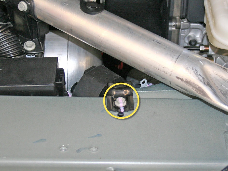
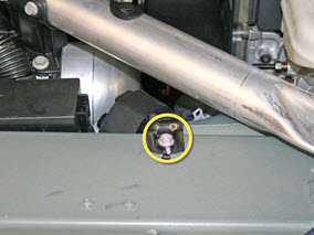
  14. Release the bolt that secures the bracket for coolant pump 3 (torque 6.5 Nm). Move the bracket behind the front crossmember.
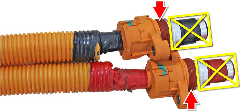
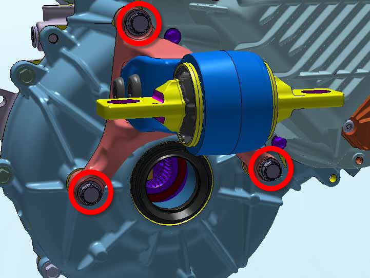
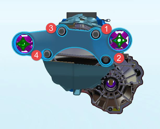
  15. Release the 4 screws that secure the HV cables to the front drive unit (torque 7 Nm).
    Caution: During reinstallation, carefully inspect the connector seals. If any are damaged, replace them.
    Caution: Apply P-80 emulsion to the connector seals on the HV cables before securing the HV cables during reinstallation.
    Caution: Do not apply P-80 emulsion to the HV terminals.
  16. Disconnect the motor logic connector.
  17. On the LH side of the underhood area, release the bracket from the body that secures the 4-way valve.
  18. Hand-tighten the drain plug and remove the fluid transfer pan.

Remove Front Drive Unit

  1. Position the support jack on top of the front crossmember and secure the 2 screws to the front crossmember.
    The support jack mounts to the bolt holes on top of the front crossmember that secured the coolant reservoir.
  2. Fully lower both mounts of the support jack.

The next 2 steps explain how to position the straps underneath the front drive unit in order to remove it with the support jack. Work from the underhood area while an assistant works from the LH wheelwell.

  1. Position the LH strap:
    1. Slide the strap between the LH motor mount and the front drive unit.
    2. Have the assistant slide the strap inward, as close to the differential housing as possible.
      Caution: Ensure that there are no coolant hoses between the strap and the front drive unit.
    3. Reach behind the front crossmember and pull the strap up and over the top of the support jack.
    4. Secure the two ends of the strap with the carabiner.
    5. Slide the strap so that the carabiner is approximately 6 in (152 mm) above the front crossmember.

Work from the underhood area while an assistant works from the RH wheelwell

  1. Position the RH strap:
    1. Lower one end of the strap over the top of the support jack and behind the front crossmember.
    2. Have the assistant position the strap underneath the drive unit, as close to the differential housing as possible.
      Caution: Ensure that there are no coolant hoses between the strap and the front drive unit.
    3. Reach beneath the drive unit and pull the strap upwards.
    4. Secure the two ends of the strap with the carabiner.
    5. Slide the strap so that the carabiner is approximately 6 inches above the front crossmember.
  2. Raise the support jack until both straps are fully taut.

Caution: Ensure that both straps are completely taut before continuing.

  1. Release the ground strap unit from the drive unit (torque 6 Nm).
  2. Raise the vehicle to access the LH wheelwell.
  3. Release the 2 bolts that secure the LH side motor mount to the body (torque 50 Nm).
  4. Disconnect the 3 electrical harnesses from the steering rack.
  5. Position the steering rack protector over the plastic housing on the LH side of the steering rack.
    Caution: Ensure that the steering rack protector completely covers the plastic housing before continuing.
  6. Remove the 3 bolts that secure the motor to the LH motor mount (torque 38 Nm):
    1. Raise the vehicle to access the LH wheelwell.
    2. Use a deep socket to release the rear bolt.
    3. Lower the vehicle.
    4. Working from the underhood area, release the front 2 bolts.
  7. Remove the LH motor mount from the vehicle.
  8. Use a driveshaft extractor to remove the LH halfshaft.
    Tip: The halfshaft might be difficult to remove. If necessary:
    • Strike the free end of the driveshaft extractor with a deadblow hammer.
    • Grip the free end of the extractor with a pair of pliers to provide additional leverage.
    • Loosen the LH bolt on the support jack to release tension on the strap, then have an assistant rotate the shaft from the wheelwell. Immediately tighten the strap on the support jack.
  9. Secure the tilt-lift extension to the crane.
  10. Set the crane to the 1.5 ton mark.
  11. Secure the crane to the front drive unit at the locations shown.

Warning: Ensure that the support jack is secured to the front crossmember and that both straps are completely taut before continuing. After this step, the entire weight of the drive unit will be supported by the support jack.

  1. Release the 4 bolts that secure the motor to the RH mount:
    Note: Not all 4 bolts can be completely removed. Loosen the bolts so that the motor is not secured to the motor mount. The RH motor mount is not removed in this procedure.
    1. Working from the underhood area, remove the front upper bolt.
    2. Working from the underhood area, release the front lower bolt.
      Note: This bolt cannot be fully removed; it is retained inside the mount threads during removal.
    3. Working from the RH wheelwell, remove the rear upper bolt.
    4. Working from the RH wheelwell, release the rear lower bolt.
      Note: This bolt cannot be fully removed; it is retained inside the mount threads during removal.
  2. Raise the motor until the top of the heat dissipater is approximately 10 mm beneath the front crossmember.
  3. Slowly raise the crane while rotating the RH side of the motor toward the LH side of the vehicle.
    Caution: Do not damage the steering rack.
  4. Once the motor is approximately halfway out of the vehicle, disconnect the electrical harness from coolant pump 4.
    Note: The coolant hose, pump, and bracket are removed with the motor.
  5. Continue removing the motor; alternate between raising the crane and lowering the support jack.
  6. Once the differential has cleared the steering rack, remove the straps from the motor so that it is supported entirely by the crane.
  7. Remove the motor from the vehicle.

Installation

  1. Use alcohol wipes to clean the mating surfaces between the RH motor mount and drive unit.
  2. Ensure that the support jack is secured to the front crossmember.
  3. With an assistant, lower the motor on the crane while pushing it into the vehicle.

Caution: Be very careful not to damage the steering rack. Ensure that the protector is still over the plastic housing on the steering rack.

  1. Secure the straps around the motor.
  2. Slide coolant pump 4 and the hose back behind the motor; these will be reinstalled in a later step.
  3. Continue to lower the motor into position, both by lowering the crane and raising the support jack.
  4. Once the crane can no longer be lowered, ensure that the support jack straps completely support the drive unit, then release the crane cables.
  5. Continue to position the motor. Have an assistant working from the RH wheelwell help to align the motor with the RH motor mount.
  6. Place the shear plate on the outboard side of the motor mount so that the shear plate bolt holes align with the motor mount bolt holes.
    Caution: Ensure that the bottom holes on the shear plate are not slotted. If the bottom holes are slotted, replace the shear plate with one that is not slotted.
  7. Loosely install the upper front bolt to secure the motor to the RH motor mount.
    Note: This allows for proper alignment of the motor.
  8. Install the lower RH section of NVH padding.
  9. Rotate the motor so that the other 3 bolt holes for the RH motor mount are aligned, but do not secure the bolts yet.
  10. Working from the underhood area, loosely install the lower front bolt.
  11. Working from the RH wheelwell, loosely install both rear bolts.
  12. Connect the harness for coolant pump 4.
    Caution: Ensure that the hose is not twisted.
  13. Secure the coolant pump bracket to the body.
    Note: These bolts appear similar to other fasteners used in this procedure, but are slightly shorter. Ensure that the correct bolts are used during reinstallation.
  14. Working from the RH wheelwell, resecure the cooling hose to the rocker hose.
  15. Have an assistant push the LH knuckle inboard while rotating it forward; install the LH axle.
    Caution: Do not damage the differential seal.
    Note: Ensure that the opening of the snap ring is facing towards the bottom of the drive unit.
    Note: Verify that the driveshaft is fully seated by carefully pushing it into the drive unit until there is an audible "click" from the snap ring.
  16. Resecure the LH knukcle to the upper control arm (torque 60 Nm).
  17. Working from the underhood area, set the LH motor mount into position and loosely install the front 2 bolts to secure it to the motor.
  18. Working from the LH wheelwell, loosely install the rear bolt to secure the mount to the motor.
  19. Tighten all 3 motor mount bolts (torque 38 Nm).
  20. Install the rear bolt and washer that secures the LH motor mount to the frame rail.
    Tip: It might be helpful to raise or lower the motor with the support jack to align the bolt.
  21. Install the front bolt and washer to secure the LH motor mount to the frame rail.
  22. Position the 3 shim tools between the RH motor mount and body.
    Note: These tools ensure that both sides of the motor mount have at least 5 mm clearance to the body.
    1. Working from the underhood area, position the 2-pronged shim around the RH motor mount front bushing.
    2. Reach beneath the motor and position the hook shim tool between the mount and outer bushing.
    3. Reach downward between the V-brace and cross brace and position the straight shim tool between the mount and inner bushing.
  23. Working from the wheelwell, use a deep socket to install the rear bolt that secures the LH mount to the drive unit (torque 38 Nm).
  24. Working from the underhood area, install the 2 front bolts for the LH mount to the drive unit (torque 38 Nm).
  25. Attach the 15 mm ratchet tool to a torque wrench.
    Caution: Ensure that the ratchet tool is 90 degrees perpendicular to the handle of the torque wrench when using the tool.
    1 90 degree angle
  26. Working from the underhood area, fully torque the 4 bolts that secure the motor to the RH mount (torque 75 Nm).
    1. Working from the underhood area, use the ratchet and torque wrench to secure the upper front bolt.
    2. Working from the wheelwell, secure the lower rear bolt.
    3. Working from the wheelwell, secure the upper rear bolt.
    4. Working from the underhood area, use the ratchet and torque wrench to secure the lower front bolt.
  27. Reinsert the shim tools to verify proper clearance between the bushings and body. If the shims do not fit, release the 3 bolts that secure the LH motor mount and repeat steps 25-27.
  28. Release the carabiners and remove the straps from the motor.
  29. Remove the support jack from the vehicle.
  30. Remove the fill plug (torque 28 Nm).
  31. Fill the drive unit with the correct amount of proper fluid:
    Caution: Use exactly the specified amount of gear oil. Do not fill to the top of the fill plug.
  32. Install the lower RH section of NVH padding.
  33. Reinstall all components that were removed for access:
    1. Remove the steering rack cover and reconnect the 3 steering rack harnesses.
    2. Reinstall the RH halfshaft.
    3. Secure the motor ground strap to the frame rail (torque 9 Nm).
      Note: Do not overtorque the nut to avoid breaking the stud on the frame rail.
    4. Reconnect the motor logic connector. Perform a push-pull-push test before proceeding to ensure that the connector is secure.
    5. Secure the bracket for coolant pump 4 to the front crossmember.
    6. Reinstall both fuse boxes.
    7. Reinstall the A/C compressor.
    8. Reinstall the 4-way bracket.
    9. Reinstall the A/C lines.
    10. Connect the LV A/C compressor harness and resecure the clip the motor.
    11. Secure the compressor ground strap.
    12. Reattach the 4 clips to secure the coolant hose to the bottom of the front crossmember, but do not secure the hoses to the motor at this time.
      Note: When securing the clips on the LH side of the front crossmember, do not use the front holes. These are for clipping the reservoir hose in a later substep.
    13. Route the coolant reservoir hose behind the hose for the differential housing, then clip the coolant reservoir hose to the front crossmember.
    14. Reconnect the coolant hoses to the differential housing and the RH side of the drive unit.
    15. Connect the coolant reservoir sensor.
    16. Secure the 4 bolts to reinstall the coolant reservoir to the front crossmember.
    17. Ensure that the coolant hose to the rear of the motor is clipped to the steering rack and subframe.
    18. Pull a vacuum on the A/C system for 15 minutes; continue this procedure while the vacuum is being pulled.
    19. Reconnect the clip to secure the A/C line to the hose.
    20. Apply P-80 emulsion to the connector seals on the HV cables, then resecure the HV cables to the motor.
      Caution: Do not apply P-80 emulsion to the HV terminals.
      Caution: Carefully inspect the connector seals. If any are damaged, replace them.
    21. Clip the 12V positive terminal to the top of the front crossmember.
    22. Install the 12V battery support brace.
    23. Reinstall the 12V battery tray.
    24. Hand tighten the bolt that secures the hose to the 12V battery support brace. and put the fir tree clips through the bracket.
    25. Resecure the fir tree clips that secure the LH A/C line to the bracket.
    26. Resecure the 2 bolts on the edges of the 12V battery support brace.
    27. Secure the 3 bolts that secure the 12V bracket to the front crossmember.
    28. Reinstall the long bolt in the back of the bracket.
    29. Reinstall the 12V battery and reconnect the 12V positive terminal.
    30. Recharge the A/C and resecure the ports.
    31. Resecure the intelligent battery sensor to the negative terminal, then reconnect the 12V negative terminal.
  34. Perform a coolant purge.
  35. Resecure the sway bar links.
  36. Reinstall all other components that were removed for access.