Removal
-
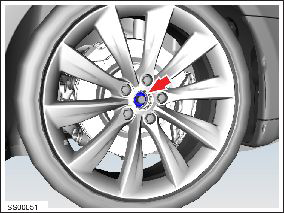
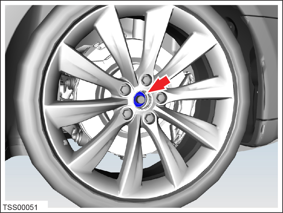
Remove the center cap from the front LH wheel and loosen the axle nut.
-
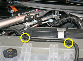
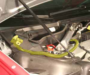
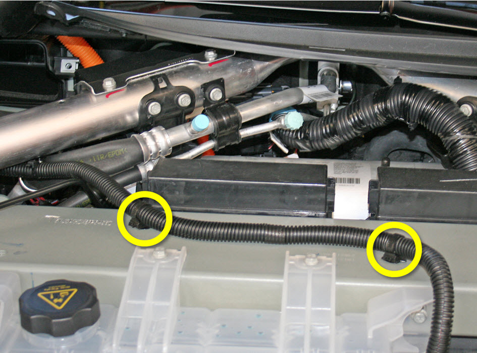
Release the 2 fir tree clips that secure the 12V positive harness to the front
crossmember.
-
Move the 12V positive harness to the RH side of the vehicle to keep it out of
the working area.
-
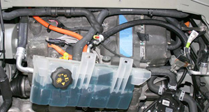
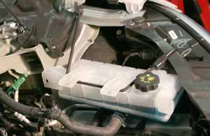
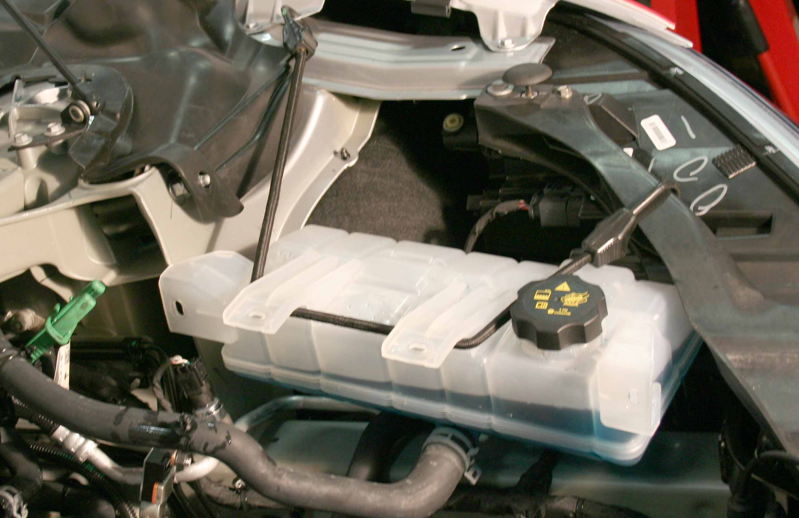
Release the 4 bolts that secure the coolant reservoir to the front crossmember
(torque 6 Nm). Do not remove the reservoir at this time.


Caution: At this point in the procedure, there are still 2 coolant hoses
and 1 harness attached to the reservoir.
-
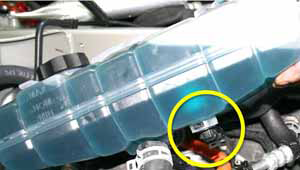
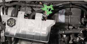
Carefully lift up the coolant reservoir and disconnect the coolant level sensor
harness.
-
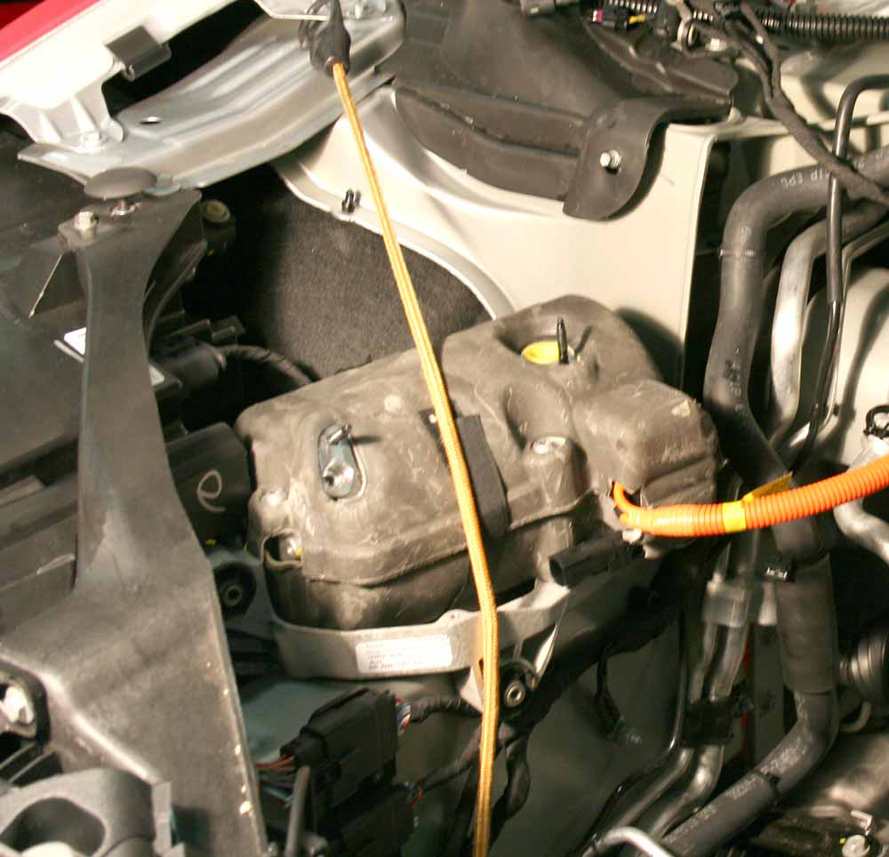
Ensure that the cap on the reservoir is properly secured, then pull the
reservoir forward into the underhood area.
Note: The reservoir hose is routed behind the drive unit hose. Note the routing of the hoses and ensure that they are routed correctly during reinstallation.
-
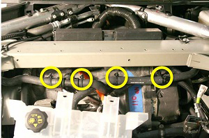
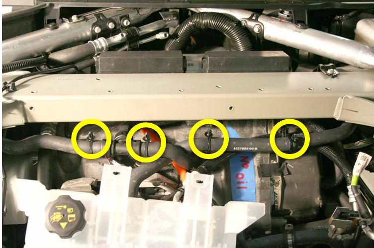
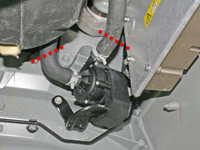
Gently pull down on the 2 coolant hoses to release the clips (x4) that secure
them to the front crossmember.
-
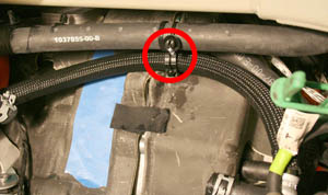
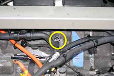
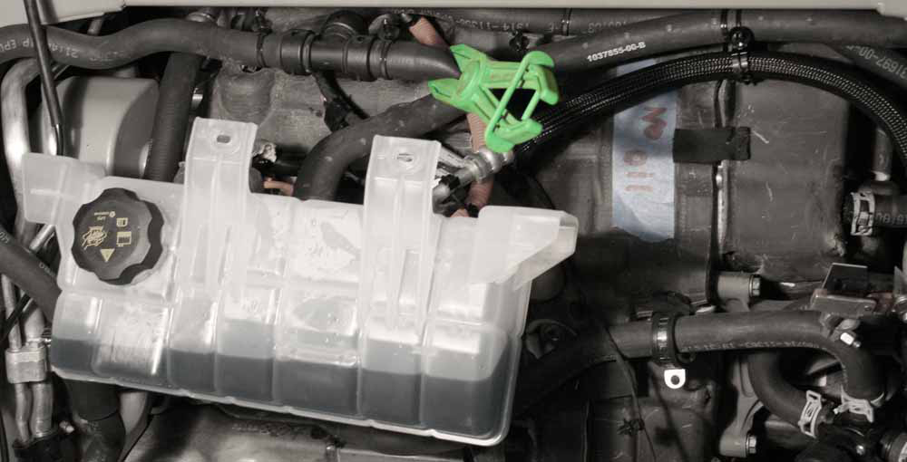
Release the clip that secures the coolant reservoir hose to the A/C line.
-
On the LH side of the 3-way fitting, clamp the coolant hose that leads to the
differential housing. Remove the hose from the front drive unit and and plug the
nipple.
-
Move the coolant reservoir to the LH side of the vehicle and secure it out of
the working area.
Caution: The reservoir is still secured to 2 coolant hoses.
-
Move the clamped drive unit coolant hose to the RH side of the vehicle so that
it is out of the working area.

-
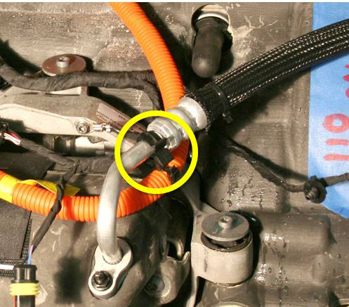
Release the clip that secures the LH A/C line to the compressor HV
harness.

-
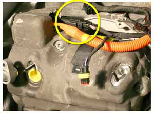
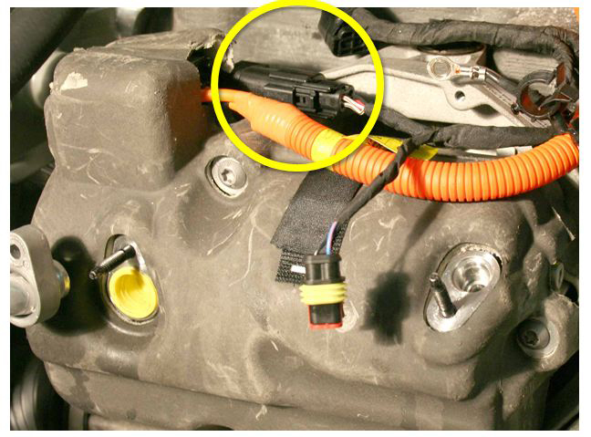
Disconnect the compressor LV harness.
-
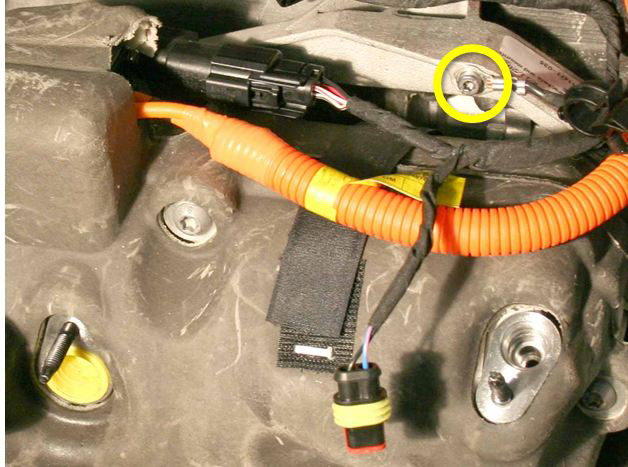
Release the ground strap from the A/C compressor bracket (torque 7 Nm).

-
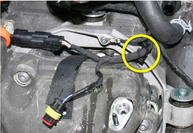
Release the edge clip that secures the LV harnesses to the compressor
bracket.

-
Release the fir tree clip that secures the LV harnesses to the top of the front
drive unit.

-
Have an assistant support the compressor. Release the 3 bolts that secure the
A/C compressor bracket to the front drive unit (torque 10 Nm).
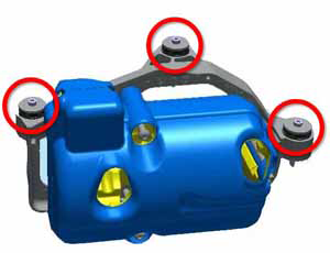


Caution: Do not spill any oil when removing the compressor.
-
Move the compressor and bracket to the RH side of the vehicle and secure them
outside of the working area.

-
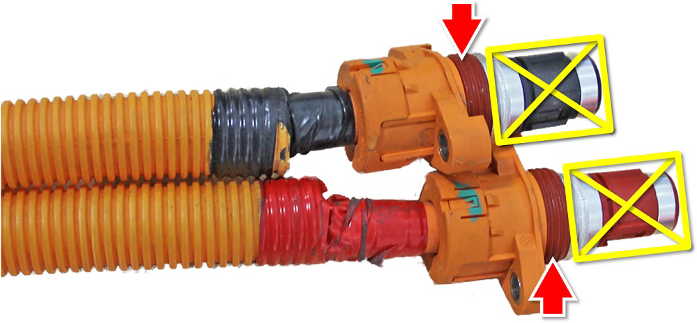
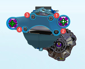
Release the 4 screws that secure the HV cables to the front drive unit (torque 7
Nm).
Caution: During reinstallation, carefully inspect the connector seals. If any are damaged, replace them.Caution: Apply P-80 emulsion to the connector seals on the HV cables before securing the HV cables during reinstallation.Caution: Do not apply P-80 emulsion to the HV terminals.
-
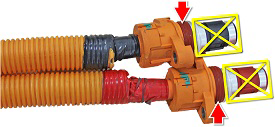
Clamp the 2 coolant hoses that lead to coolant pump 4.
-
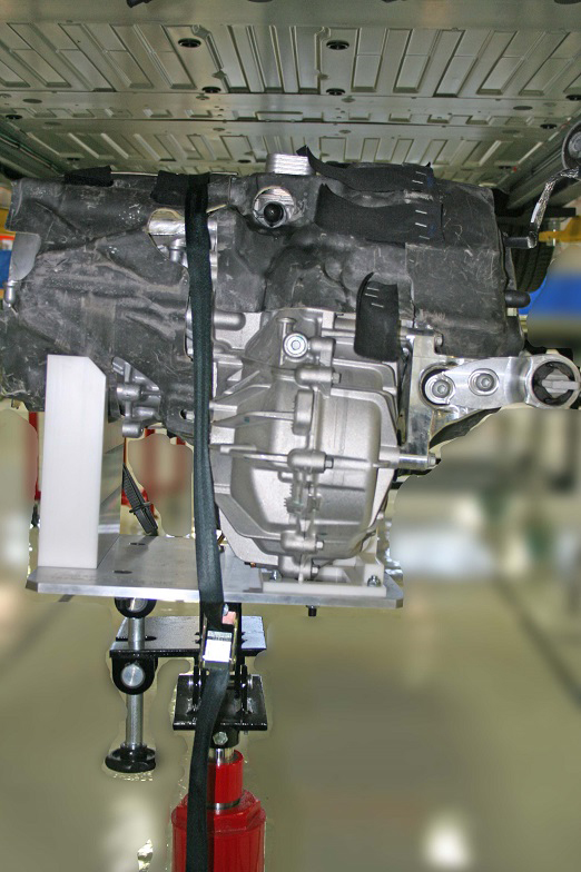
Install the drive unit cradle onto the transmission jack.
Non-European jack shown

-
Raise the transmission jack to support the weight of the drive unit. Ensure that
the ridge on the base of the drive unit fits into the channel on the transmission
jack.


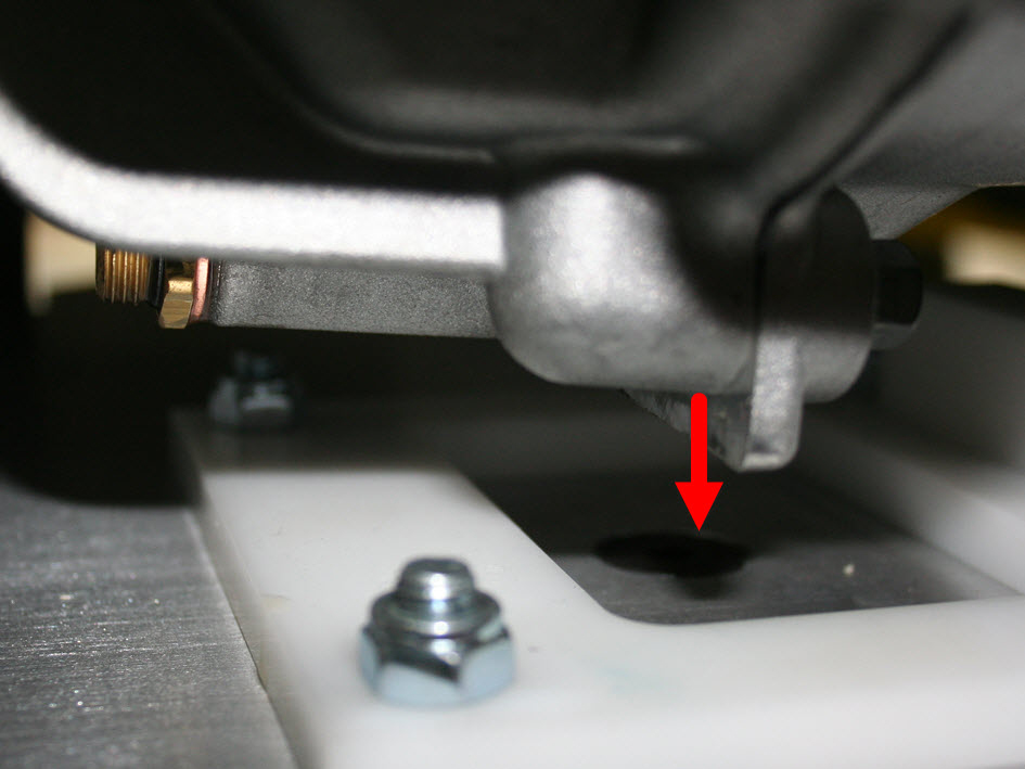
Caution: Before continuing, ensure that the entire weight of the drive
unit is supported by the transmission jack.
-
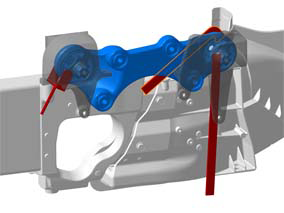
Release the bolts (x4) that secure the motor to the RH mount.
Note: Do not fully remove the bolts from the mount; loosen the bolts in the order shown so that the motor is no longer supported by the mount. The RH motor mount is not removed in this procedure.
-
Lower the transmission jack and secure the drive unit with the strap.