Removal
-
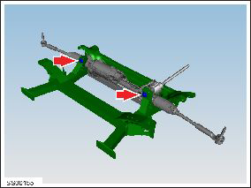
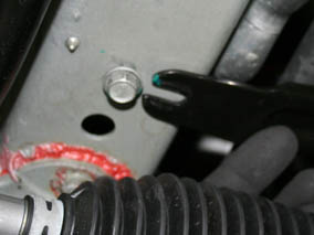
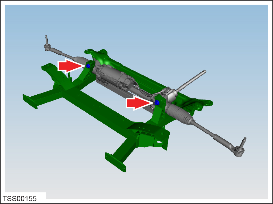
Release the bolts (x2) that secure the steering rack to the subframe (torque 175
Nm).
-
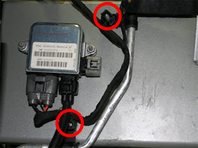
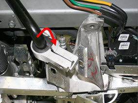
On both sides of the vehicle, remove the bolt that secures the steering brace to
the subframe (torque 26 Nm).
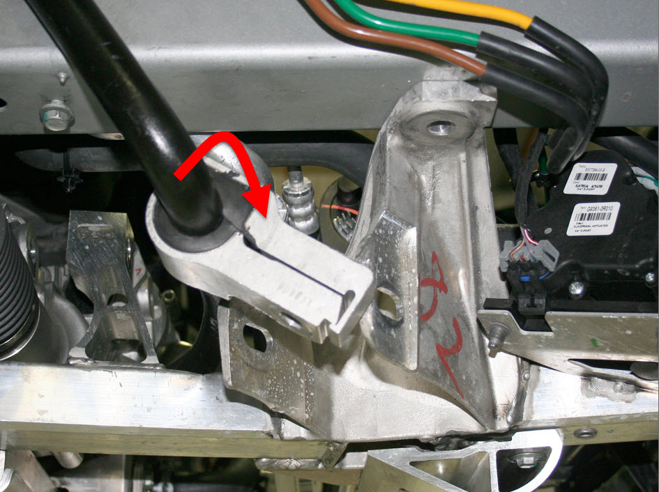
-
On the RH side of the vehicle, release the fir tree clip that secures the
coolant hose to the steering brace.

-
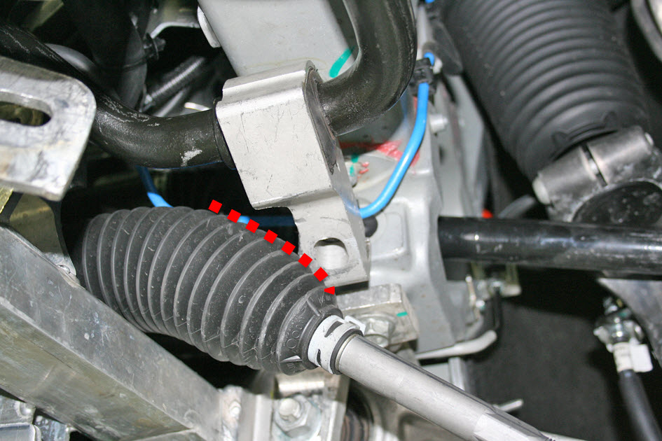
On both sides of the vehicle, restrain the tie rod ball joint pin, then remove
the nut that secures the tie rod end to the knuckle (torque 103 Nm).
Caution: To prevent ball joint damage, always hold the ball joint pin with a wrench while loosening or tightening the lock nut.

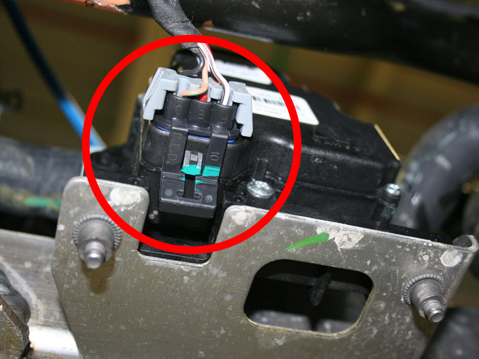
-
Working from beneath the vehicle, remove the connector from the base of the 3
way valve.

-
Release the edge clip that secures the 3 way valve harness to the subframe. Move
the harness above the sway bar and out of the working area.

-
Working in the LH wheelwell, release the cable ties (x2) that secure the fan
control module harness to the side rail.
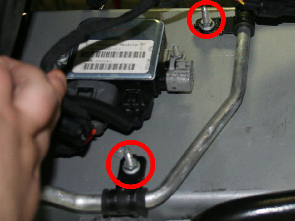
-
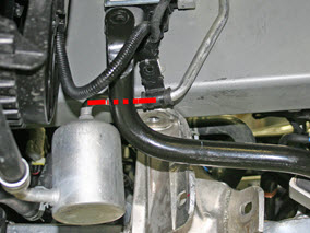
Remove the nuts (x2) that secure the A/C line to the side rail (torque 5.5
Nm).

-
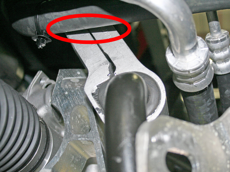
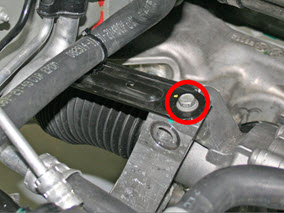
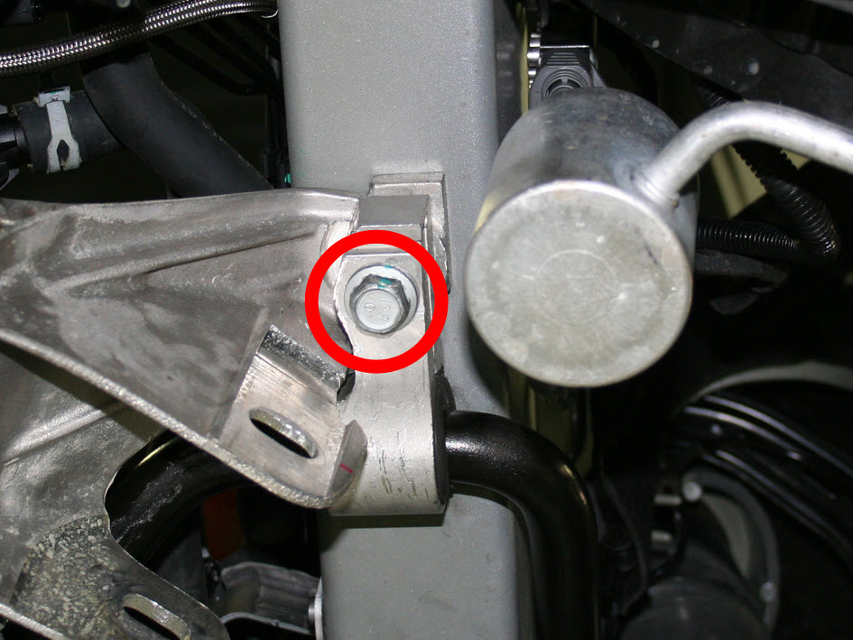
On the RH side of the vehicle, loosen the bolt that secures the steering brace
to the base of the side rail (torque 26 Nm), then remove the brace.
Note: Do not remove the bolt.
-
Note: This step is for air suspension vehicles only.On the LH side of the vehicle, release the clip that secures the air suspension line to the steering brace.
-
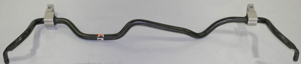
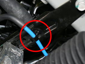
On both sides of the vehicle, remove and discard the bolt that secures the sway
bar to the sway bar end links (torque 70 Nm).

-
On both sides of the vehicle, remove and discard the bolt that secures the sway
bar bracket to the base of the side rail (torque 115 Nm).


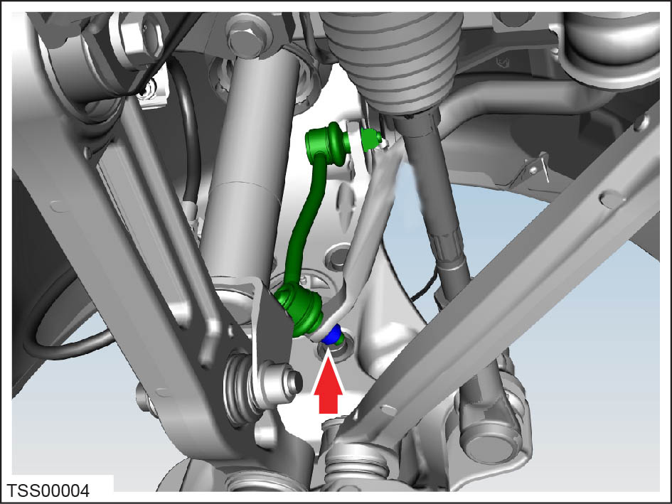
Note: The bracket is part of the sway bar; it cannot be removed. The remaining steps
explain how to manipulate the sway bar to provide clearance for the brackets,
which allow the sway bar to be removed from the LH wheelwell.
-
Working from the RH wheelwell, rotate the sway bar forward.
 Note: The bar rotates freely until the LH sway bar bracket is blocked by the subframe.
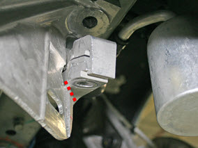
-
Use a pry bar to provide clearance between the subframe and LH sway bar bracket.
Caution: Do not damage the subframe.

-
Continue rotating the sway bar forward. Ensure that:
- The sway bar does not damage the A/C line on the LH side rail.

- Air suspension vehicles only: The sway bar does not damage the air
suspension lines on the RH side rail.

- The sway bar does not damage the A/C line on the LH side rail.
-
On both sides of the vehicle, pivot the sway bar bracket over the tie rod.
Caution: Do not damage the tie rod boot.

-
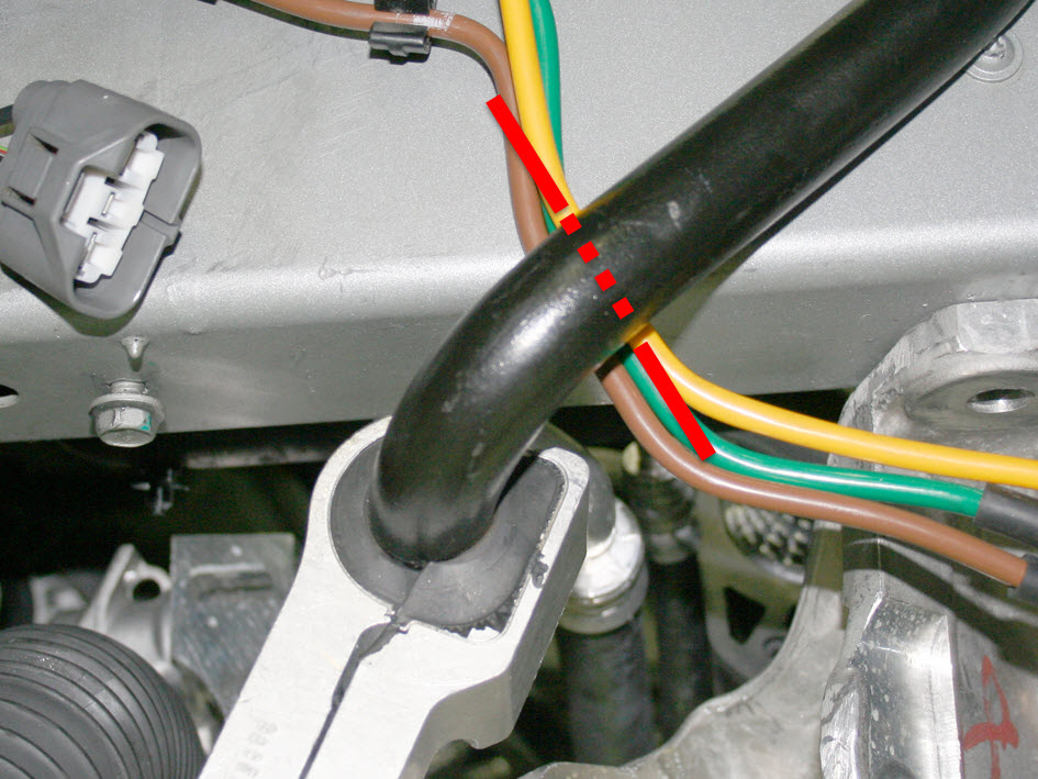
Working from the RH wheelwell, push the sway bar inboard and route it underneath
the coolant hose.

-
Maneuver the LH sway bar bracket so that it does not damage the coolant hose,
harness, or air suspension line (if equipped).
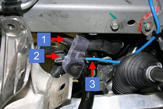
1 Coolant hose 2 Harness 3 Air suspension line -
Completely remove the sway bar from the vehicle.