Slave Charger - LH - 1st Generation (Remove and Replace)
FRT No: 44100102
Note: This procedure describes how to remove and install the 1st generation slave charger.
If the vehicle is equipped with a 2nd generation slave charger, refer to procedure
44102102 (refer to procedure).
Warning: Only technicians who have been
trained in High Voltage Awareness are permitted to perform this procedure.
Proper personal protective equipment (PPE) and insulating HV gloves with a
minimum rating of class 00 (500V) must be worn any time a high voltage cable is
handled. Refer to Tech Note TN-15-92-003, "High Voltage Awareness Care Points"
for additional safety information.
Warning: To avoid personal injury, eye protection
must be worn while using compressed air.
Removal
Note: The slave charger is optional equipment. This procedure describes replacement of a
failed slave charger. To install a slave charger in a vehicle that is only equipped
with 1 charger, refer to Service Bulletin SB-12-44-005.
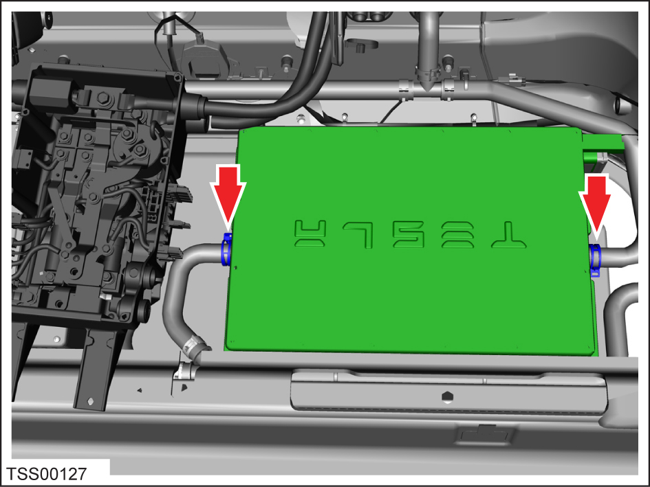
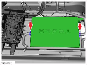
Disconnect the low voltage harness connector from the slave charger.
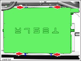
Remove the nuts (x4) that secure the charger to the body (torque 6.5 Nm).
Remove the bolt that secures the ground strap to the charger case (torque 6.5
Nm).
Position the ground strap aside.
Clamp both coolant hoses near the charger to minimize coolant loss.
Remove the coolant plug from the inboard side of the replacement charger and
have it ready before performing the next step.
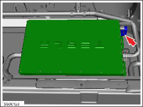
Note: Place suitable absorbent material
around the affected area to absorb any possible fluid spillage.
Tilt the inboard side of the charger upwards. Remove the coolant hose from the
charger and immediately insert the coolant plug into the charger to stop coolant
from spilling out.
Repeat steps 7-8 on the outboard coolant hose.
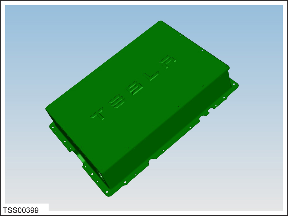
Remove the slave charger.
If the charger is being shipped or stored, allow the coolant to drain from the
charger, then use compressed air lightly to blow out any remaining coolant.
Caution: Do not exceed 25 PSI when using compressed air to blow out
any remaining coolant.
Installation
Installation procedure is the reverse of removal, except
for the following:
After the HV junction box and slave charger are reinstalled, restore power to
the vehicle by reversing the Electrical Isolation procedure.
Note: Do not reinstall the rear seat cushion yet.
Connect a laptop with Toolbox to the Ethernet port and powertrain CAN bus.
Use the Toolbox "Charger Config" panel to configure the master charger:
Use the Toolbox "Resets" panel to reset the Gateway.