Removal
Note: The slave charger is optional equipment. This procedure describes replacement
of a failed slave charger. To install a slave charger in a vehicle that is only
equipped with 1 charger, refer to Service Bulletin SB-13-44-010.
-
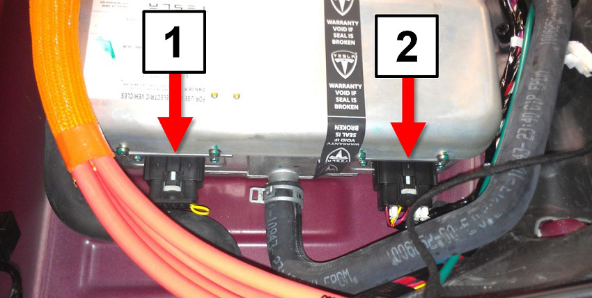
Disconnect the connectors (x2) from the side of the slave charger in the
following order:
Caution: Disconnecting harnesses in the wrong order triggers multiple high-priority alerts.
- Disconnect the 12-pin harness from the rear port.
- Disconnect the 10-pin HVIL loopback connector from the front port.
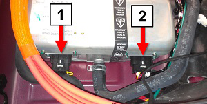
1 10-pin HVIL loopback connector 2 12-pin harness
Warning: The previous step contains instructions to check for high
voltage inside the HVJB. Do not proceed unless no high voltage is present.
-
Release the 4 harnesses that connect the HVJB to the chargers.

-
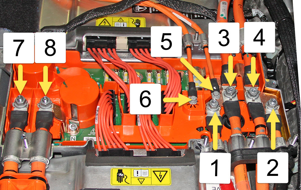
Release all fasteners inside the High Voltage Junction Box (HVJB) so that it can
lifted up in order to replace the charger in a later step:
-
Dual motor vehicles only: Mark the rear HV cable that leads to the
front drive unit as B-, and the forward HV cable that leads to the front
drive unit as B+.
Table 1: HV Cable fasteners inside HVJB

1 B+ Front Drive Unit (if equipped) 2 B- Front Drive Unit (if equipped) 3 B+ battery/drive inverter 4 B- battery/drive inverter 5 B+ forward junction box 6 B- forward junction box 7 B- charge port 8 B+ charge port -
Mark the HV cables that lead to the charge port:
- Single-phase charging: : Mark the forward cable as B- and the rear cable as B+.
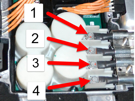
- 3-phase charging: : Starting from the front and working toward the rear of the vehicle, mark the 4 HV cables that lead to the charge port from front to rear as L2, L3, L1, and N.
Note: Vehicles equipped with 3-phase charging have 4 charge port cables instead of 2.Table 2: 3-Phase charge port cables

1 B+ N charge port 2 B- L1 charge port 3 B+ L3 charge port 4 B- L2 charge port
-
Dual motor vehicles only: Mark the rear HV cable that leads to the
front drive unit as B-, and the forward HV cable that leads to the front
drive unit as B+.
-
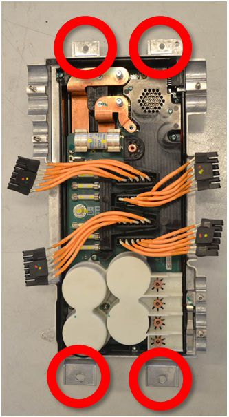
Release the 4 bolts that secure the HVJB to the body (torque 5 Nm).
Note: Do not remove the HVJB from the vehicle. It is only necessary to release the bolts so that the HVJB can be lifted up in a later step.
HVJB shown removed from vehicle, for clarity.

-
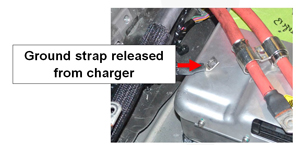
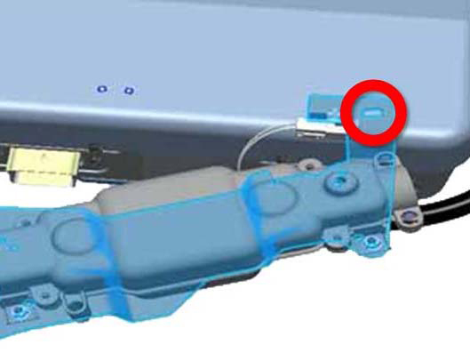
Release the ground strap from the rear of the charger (torque 7 Nm).
Note: Leave the ground strap secured to the vehicle.
-
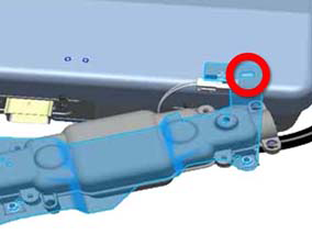
Dual motor vehicles only: Release the bolt that secures the fuse bracket to the
slave charger (torque 9 Nm).
-
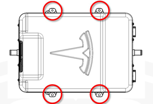
Release the 4 bolts that secure the charger to the body (torque 7
Nm).


Note: It is necessary to lift the front of the HVJB out of the way in order to access
the inboard coolant hose. Have an assistant hold up the front of the HVJB 20-30
mm.
-
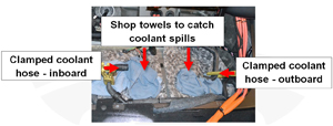
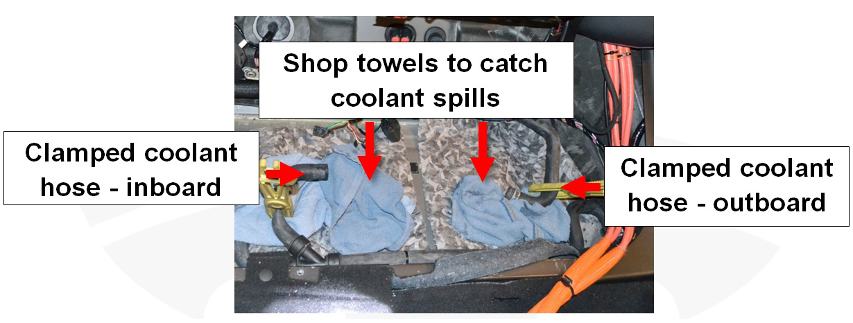
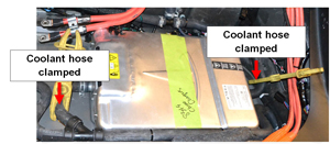
Clamp the coolant hoses on both the inboard and outboard sides of the
charger, approximately 150 mm from the edge of the charger.
-
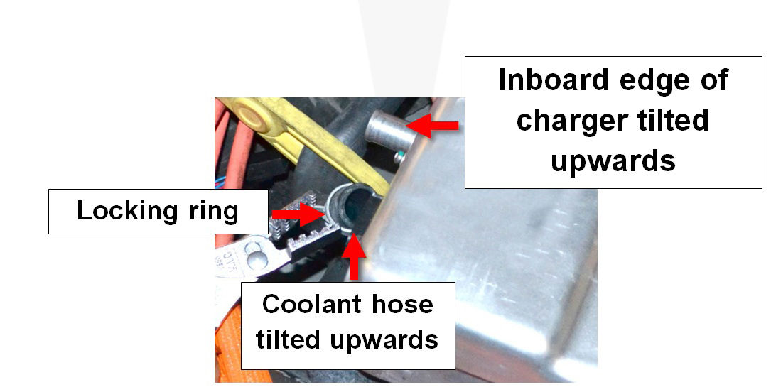
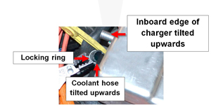
Tilt the inboard edge of the charger upwards. Use pliers or a similar tool
to release the locking ring from the inboard coolant hose. Remove the
coolant hose from the new charger and immediately install the coolant plug
onto the old charger to stop coolant from spilling out.
-
Lift the charger out of the vehicle.