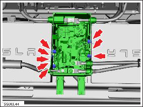
HV Junction Box - 1st Generation (Remove and Replace)

FRT No: 44300102

Warning: Only technicians who have been trained in High Voltage Awareness are permitted to perform this procedure. Proper personal protective equipment (PPE) and insulating HV gloves with a minimum rating of class 00 (500V) must be worn any time a high voltage cable is handled. Refer to Tech Note TN-15-92-003, "High Voltage Awareness Care Points" for additional safety information.

Removal

Note: The Slave charger is not installed on all vehicles, but it may appear in the graphics for this procedure.
  1. Perform the vehicle electrical isolation procedure (refer to procedure).
  2. Remove the HVJB cover (refer to procedure).
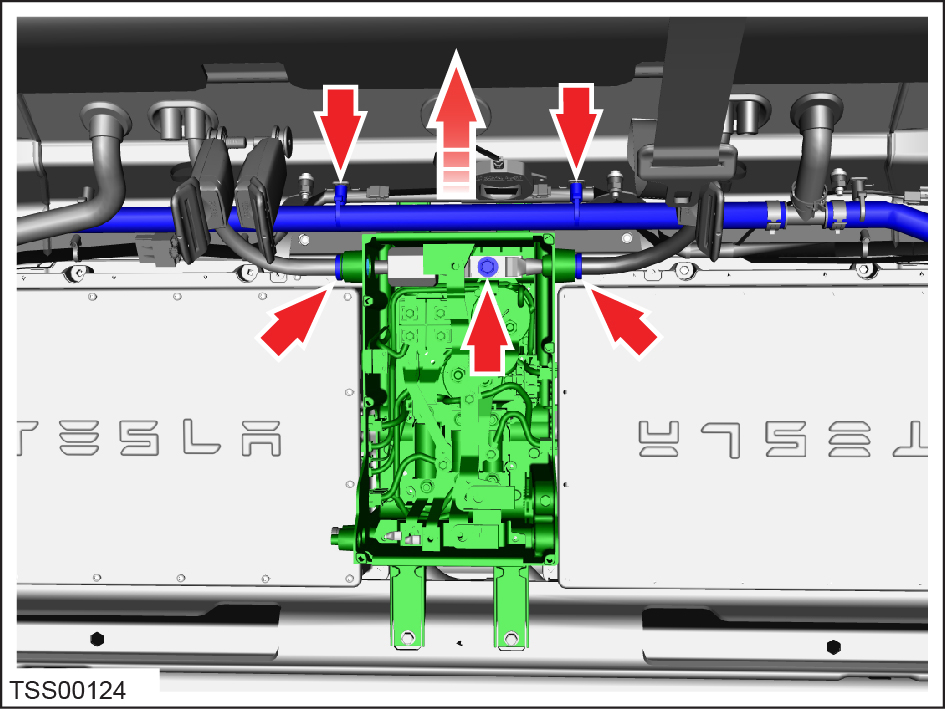
  3. Position the coolant hose aside to access to the HV junction box bracket bolts.
  4. Release the clips (x2) that secure the charger coolant hose to the heel board.
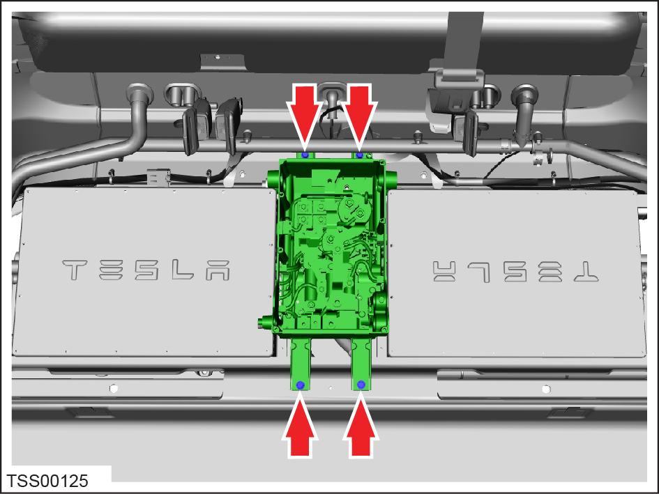
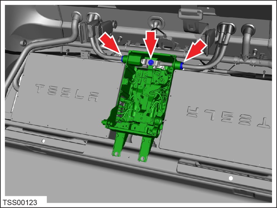
  5. Remove the bolts (x4) that secure the HV junction box (torque 5 Nm).
  6. Disconnect the junction box to slave charger connectors (x2).
    Note: Note installed position of components before removal.
    Note: Lower specification vehicles do not have this component installed.
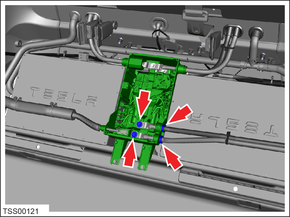
  7. Disconnect the High Voltage Interlock (HVIL) loop connector and position it aside.
  8. Disconnect the junction box to master charger connectors (x5).
    Note: Note installed position of components before removal.
  9. Carefully lift the junction box and support it on a block to gain access to connectors.
  10. Remove the bolts (x2) that secure the positive and negative charge port cables at the HV junction box (torque 9 Nm).
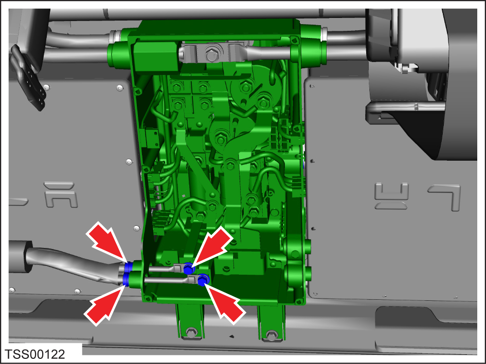
  11. Release the quick connectors (x2) that secure the charge port cables to the HV junction box body, then move the cables aside.
  12. Remove the bolts (x2) that secure the DCDC positive and negative cable terminals to the HV junction box (torque 9 Nm).
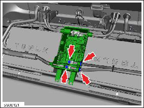
  13. Release the quick connectors (x2) that secure the DCDC cables to the HV junction box body, then move the cables aside.
  14. Remove the bolt that secures the drive inverter and HV battery positive cables to the HV junction box (torque 9 Nm).
  15. Release the quick connectors (x2) that secure the drive inverter and HV battery positive cables to the HV junction box body, then move the cables aside.
  16. Remove the bolt that secures the drive inverter and HV battery negative cables to the HV junction box (torque 9 Nm).
  17. Release the quick connectors (x2) that secure the drive inverter and HV battery negative cables to the HV junction box body, then move the cables aside.
  18. Remove the bolt that secures the ground strap to the HV junction box (torque 5 Nm).
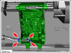
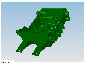
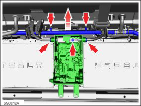
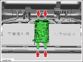
  19. Remove the HV junction box.

Installation

Installation procedure is the reverse of removal.