HV Harness - Rear Drive Unit to HVJB

FRT No: 44500902

Warning: Only technicians who have been trained in High Voltage Awareness are permitted to perform this procedure. Proper personal protective equipment (PPE) and insulating HV gloves with a minimum rating of class 00 (500V) must be worn any time a high voltage cable is handled. Refer to Tech Note TN-15-92-003, "High Voltage Awareness Care Points" for additional safety information.

Special tools required for this procedure:

Supplier Part Number Description
Tesla 1051629-00-A Cap, Connection, Rosenberger, H4Z001-000/52

Removal

  1. Position the vehicle in preparation for raising it, but keep the vehicle at ground level at this time.
  2. Perform the vehicle electrical isolation procedure (refer to procedure).
  3. Remove the high voltage junction box (HVJB) cover (refer to procedure).

Warning: Perform all of the voltage checks listed in the procedure. If any voltage reading is more than 10V, the high voltage contactors are not fully opened. Due to the risk of electrocution, contact Service Engineering before performing any further work.

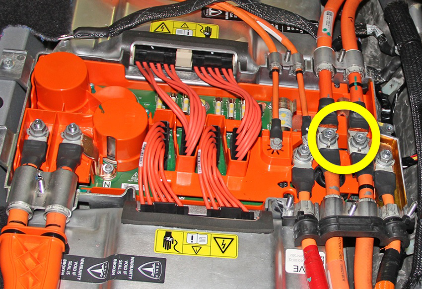
  1. Remove the nuts (x2) that secure the B+ and B- HV cables to the HVJB (torque 9 Nm).
    Note: It is not necessary to replace the fastener(s) after it is removed. The threaded area has a reusable dry sealant, which looks similar to adhesive patch material.
  2. Remove the bolt that secures the HV fuse ground strap to the body (torque 5.5 Nm).
  3. Release the edge clips (x2) that secure the HV harness to the body of the vehicle.
  4. Carefully release the grommet from the body.
  5. Remove the mid aero shield (refer to procedure).
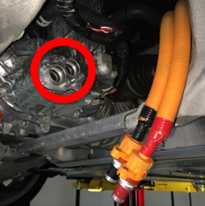
  6. Remove and discard the screws (x4) that secure the B+ and B- HV cables to the rear drive unit (torque 7 Nm).
  7. Install protective caps over both HV cables to protect the terminals and seals.
  8. Release the cable ties (x2) that secure the HV cables to the body of the vehicle.
  9. Lower the vehicle.
  10. Working from inside the vehicle, remove the HV harness.

Installation

Installation procedure is the reverse of removal, except for the following:
Caution: Replace all Patchbolt(s).
  • Apply P-80 emulsion to the cable grommet and ensure that grommet is fully seated.
  • Apply P-80 emulsion to the connector seals on the HV cables before securing the HV cables to the drive unit.
    Caution: Do not apply P-80 emulsion to the HV terminals.