Drive Unit - Rear - Small (Remove and Install)

FRT No: 40016001

Special tools required for this procedure:

Caution: Use the specified coolant only. In this manual, refer to General Information > Capacities, Fluids, and Lubricants > Fluids.
Supplier Part Number Description
Tesla 1056361-00-A Oberg Tilt-Lift
Tesla 1046674-00-C COVER, HV, INV, 3.0-150
Tesla 1057312-00-A Axle Extractor
Note: New drive units are shipped with 1046674-00-C.

Removal

  1. Remove the rear subframe (refer to procedure).

Note: Before continuing, move the subframe fixture to the gantry.

  1. Place a coolant catcher under the subframe fixture.

Note: The 2 coolant hoses that are still attached to the drive unit are removed as an assembly.

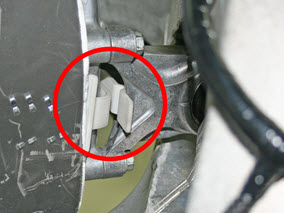
  1. Release the clip that secures the coolant hoses to the subframe.
  2. Release the clip that secures the low voltage harness to the coolant hoses.
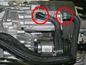
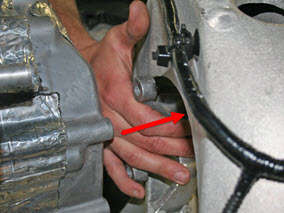
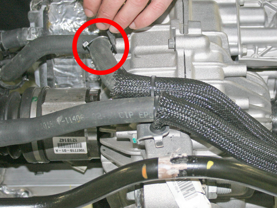
  3. At the front of the drive unit, release the bolt that secures the coolant hose bracket (torque 5.5 Nm).
  4. Plug the holes for the HV cables.
    Caution: Do not allow coolant to enter the openings for the HV cables.
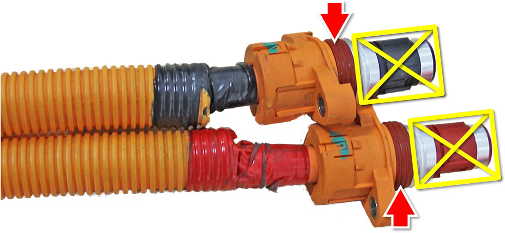
  5. Release the 2 coolant hoses from the front LH side of the drive unit.
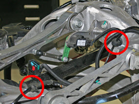
  6. Release the 2 coolant hoses from the RH side of the drive unit.
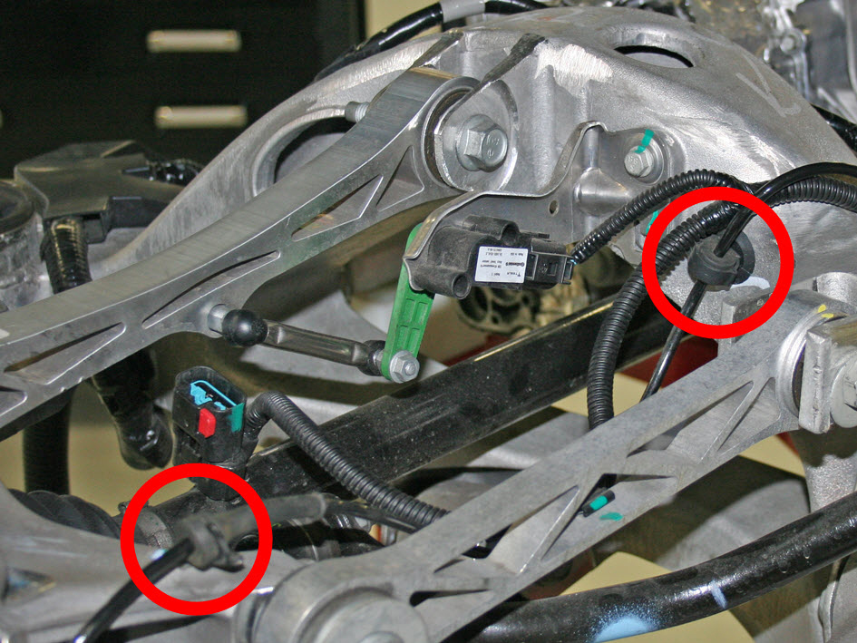
  7. On each side of the subframe, release the 2 grommets that secure the wheel speed sensor harness.
  8. On each side of the subframe, release the bolt that secures the upper link to the knuckle (torque 140 Nm).
  9. On each side of the subframe, release the bolt that secures the toe link to the knuckle (torque 130 Nm).
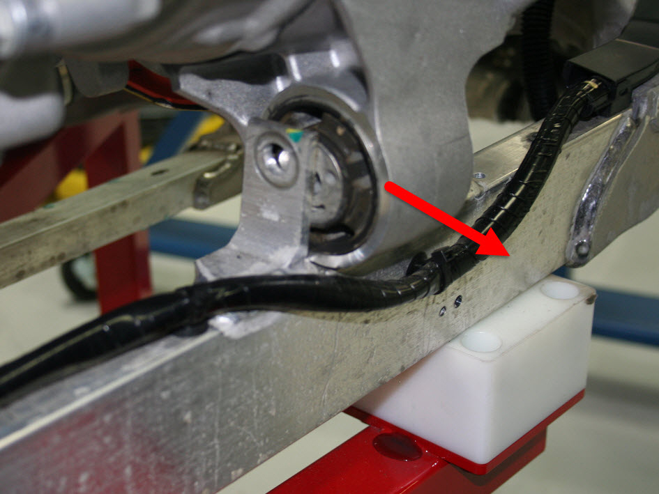
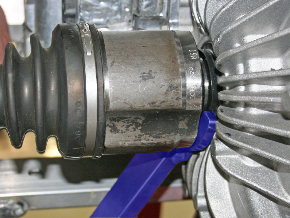
  10. Use the axle extractor tool to release the driveshafts from the transmission.
    Caution: Do not let the driveshafts rest on the input seal.
    Note: When releasing the RH driveshaft, position the tool at the bottom of the driveshaft.
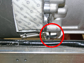
  11. Remove and discard the cable tie that secures the NVH pad to the drive unit.
  12. Remove the NVH pad from the LH side of the drive unit:
    1. Working from behind the drive unit, release the hook-and-loop straps that secure the NVH pad.
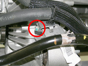
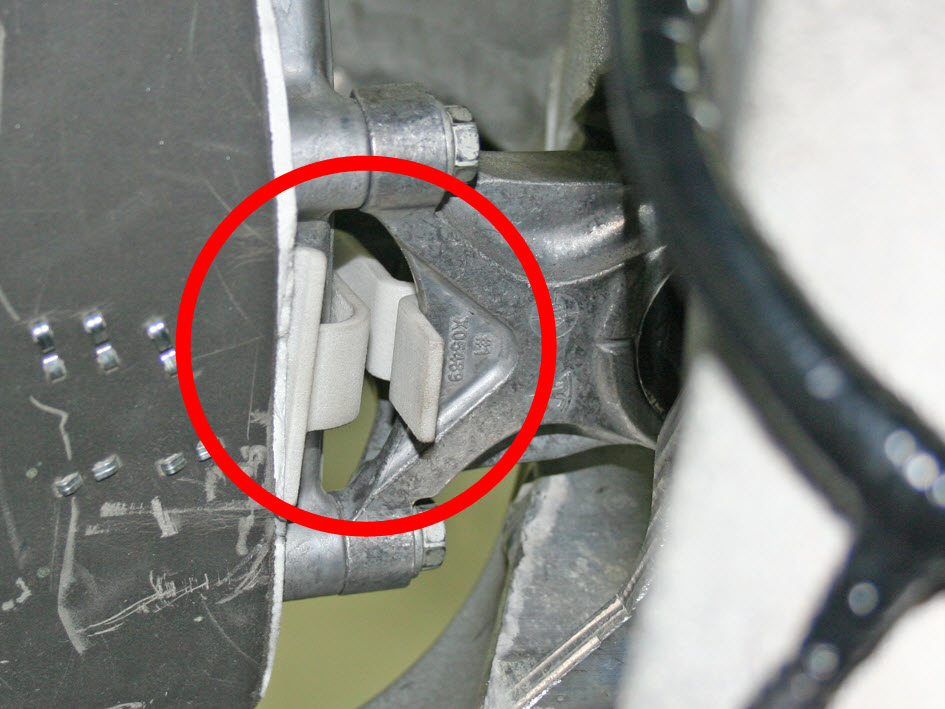
    2. Working from in front of the drive unit, remove the clip that secures the NVH pad to the LH side motor mount.
    3. Pull the NVH pad outboard to remove it.
  13. Remove the bolt that secures the front of the drive unit to the subframe (torque 90 Nm).
  14. Remove the bolt that secures the rear of the drive unit to the subframe (torque 90 Nm).
  15. Release the 3 bolts that secure the LH side motor mount to the drive unit (torque 22 Nm).
    Note: This causes the LH side of the drive unit to drop slightly.
  16. Remove the bolt that secures the LH side motor mount to the subframe (torque 90 Nm).
  17. Push the LH side motor mount outboard.
  18. Secure the tilt-lift extension to the crane.

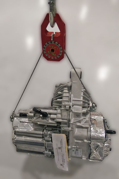
Note: To secure the tilt-lift extension to the drive unit use Tesla P/N 1016260-00-A or an equivalent M8x1.25x20mm long, class 10.9, high strength bolt.

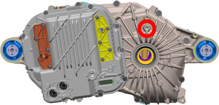
  1. Secure the tilt-lift extension to the LH side of the drive unit.
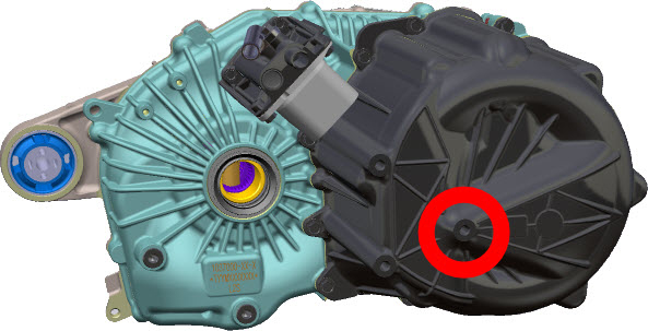
  2. Secure the tilt-lift extension to the RH side of the drive unit.

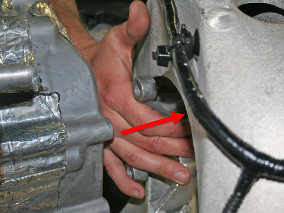
Caution: While lifting the drive unit assembly in the next step, have an assistant brace a screwdriver or similar tool against the subframe and hold the sway bar out of the way. Do not brace the tool against the motor mount.

  1. Lift the drive unit out of the subframe.

Installation

Installation procedure is the reverse of removal, except for the following:
Caution: Replace all nylon-insert locknuts.
Caution: Only fully tighten the suspension bushing bolts when the vehicle is in ride height position.
Caution: During reinstallation, carefully inspect the connector seals. If any are damaged, replace them.
  • When installing the driveshaft into the drive unit:
    • Ensure that the opening of the snap ring is facing towards the bottom of the drive unit.
    • Do not damage or displace the oil seal.
    • Verify that the driveshaft is fully seated by carefully pushing it into the drive unit until there is an audible "click" from the snap ring.
  • Apply P-80 emulsion to the connector seals on the HV cables before securing the HV cables to the drive unit.
    Caution: Do not apply P-80 emulsion to the HV terminals.
  • When lowering the drive unit, do not align the rear mount on the drive unit with the mounting hole in the subframe. Instead, pull the rear mount beyond the rear subframe. This provides enough clearance for the front of the drive unit to rotate into position as the subframe is lowered.
  • Secure the front and rear mount bolts, then secure the side mount bolt.
  • If both the front and rear drive units were removed at the same time, the vacuum refill tool must be used to refill the cooling system (refer to procedure).
  • Refill the gearbox with the recommended fluid. In this manual, refer to General Information > Capacities, Fluids, and Lubricants > Fluids.
  • Perform a four wheel alignment (refer to procedure).