Removal
-
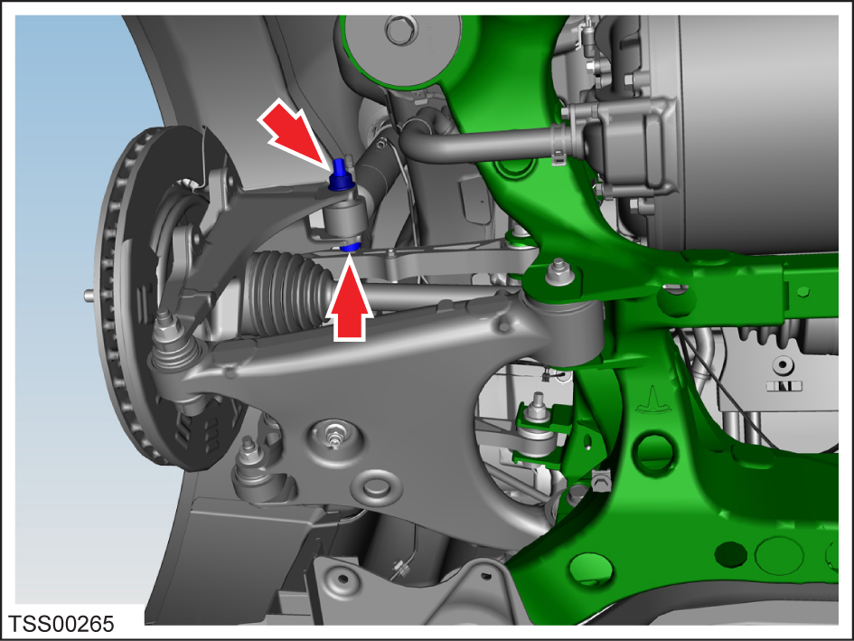
On both sides of the vehicle, remove the nut that secures the shock absorber to
the knuckle (torque 140 Nm), but do not remove the bolt yet.

-
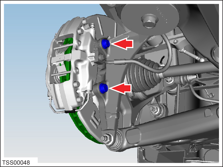
On both sides of the vehicle, loosen the bolts (x2) that secure the brake
caliper to the knuckle (torque 120 Nm). Remove and support the
calipers.
Caution: To avoid damage to the brake line, the brake caliper must be supported at all times.

-
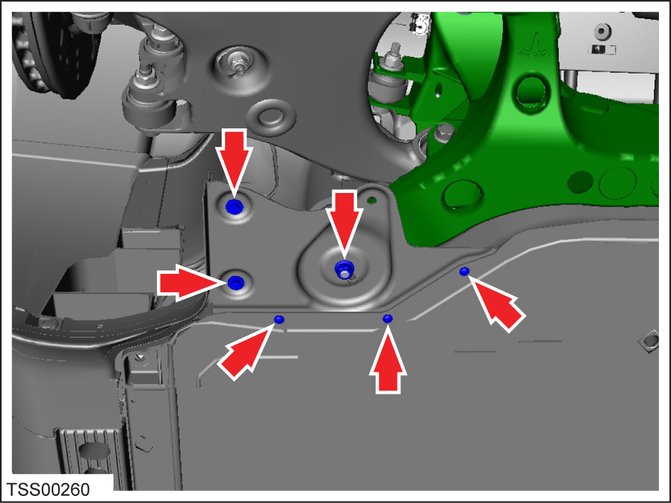
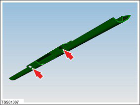
Remove the subframe shear plates by removing the nut (torque 35 Nm), clips (x2),
and screws (x3) (torque 6 Nm) that secure each shear plate to the subframe.

-
If equipped, remove the screws (x2) that secure the rear skid plate to the
subframe (torque 10 Nm).
-
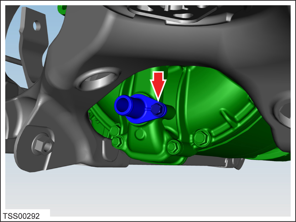
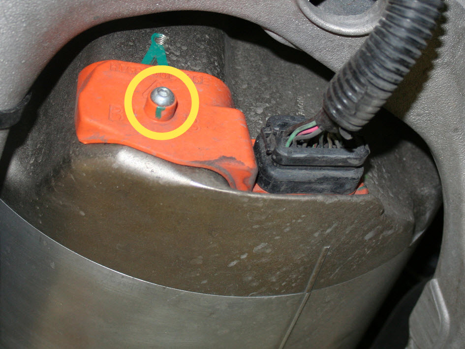
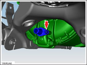
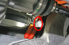
Large drive unit only: Remove the bolt that secures the coolant nipple to
the coolant manifold (torque 6 Nm).
Note: If the drive unit is being replaced, apply lubricant to the O-ring and transfer the nipple to the new drive unit.
-
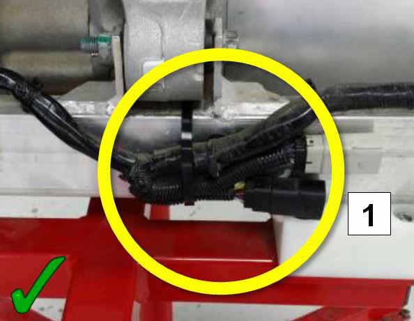
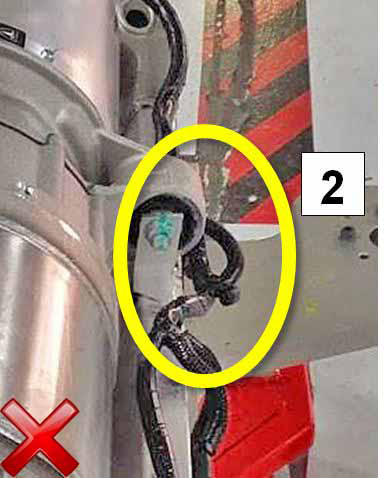
Release the clips that secure the HV cables:
- Large drive unit: 2 clips to the subframe
- Small drive unit: 2 clips to the body
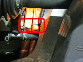
- Large drive unit: 2 clips to the subframe
-
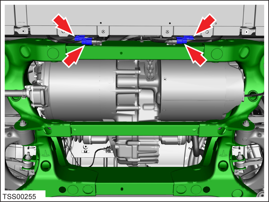
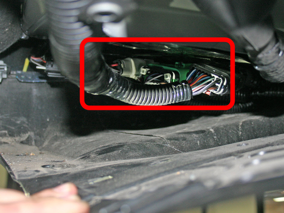
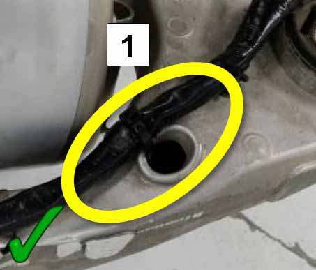
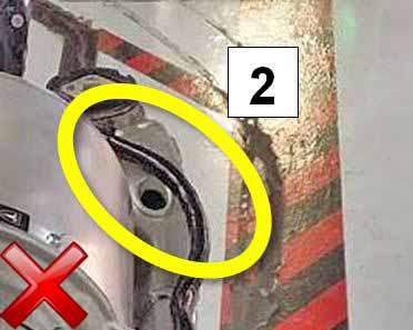
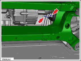
Disconnect the subframe harnesses from the body harness.
- Vehicles built through September 2014: 4 connectors at the back of
the rear subframe
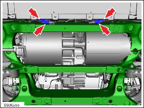
- Vehicles built after September 2014: 3 connectors above the RH side
of the rear undershield

- Vehicles built through September 2014: 4 connectors at the back of
the rear subframe
-
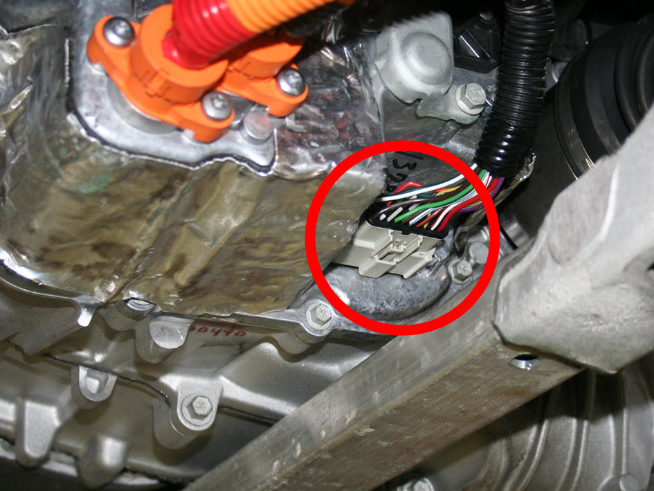
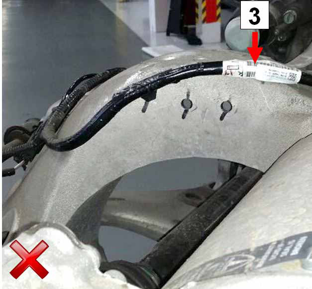
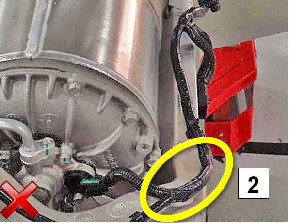
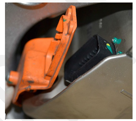
On the RH side of the drive unit, disconnect the logic connector.
- Large drive unit:
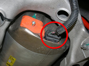
- Small drive unit:

- Large drive unit:
-
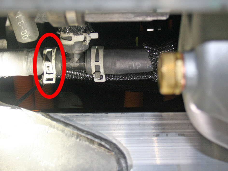
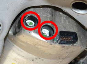
Release the HV inverter cables (x2).
- Large drive unit:
- Release the bolt that
secures the drive inverter cover (torque 3 Nm).

- Remove both O-rings from the drive inverter cover and discard.
- Release the 2 fasteners
that secure the HV cables (torque 9 Nm). Do not remove the cables at this
time.
- Release the bolt that
secures the drive inverter cover (torque 3 Nm).
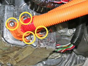
- Small drive unit:
Remove and discard the 4 screws that retain the HV cables (torque 7 Nm).
Move the cables away from the drive unit.
- Large drive unit:
-
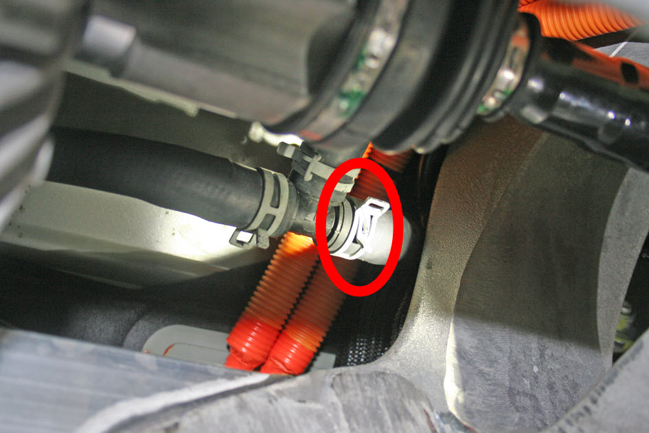
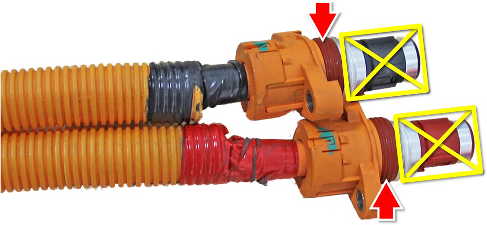
Drain the coolant from the drive unit.
- Large drive unit: Clamp and release the hoses from the transmission and drive inverter.
- Small drive unit: Clamp and release the hoses from the T-junctions
on each side of the drive unit.Note: During removal of the subframe, 2 coolant hoses remain attached to the drive unit.
LH side

RH side
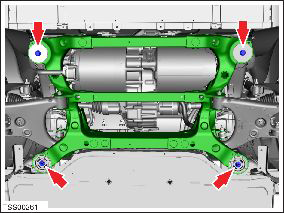
-
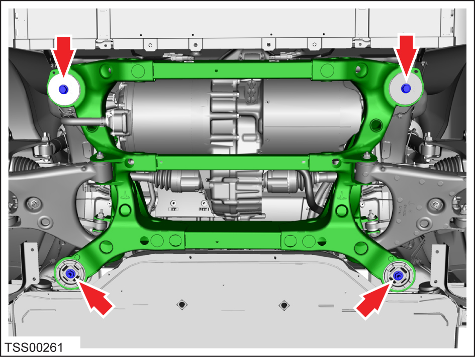
Remove the bolts (x4) that secure the rear subframe to the body (torque 140
Nm).