Drive Unit - Rear - Large (Remove and Install)

FRT No: 40012001

Special tools required for this procedure:

Supplier Part Number Description
Tesla 1000991

Axle Extractor

Note: Use 1000991 for a large drive unit only.
Tesla 1057312-00-A

Axle Extractor

Note: Use 1057312-00-A for either a large or small drive unit.

Removal

  1. Remove the rear subframe (refer to procedure).

Note: Before continuing, move the subframe fixture to the gantry.

  1. Disconnect the motor encoder.
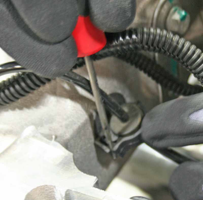
  2. Release the wheel speed sensor harnesses from the grommets on the subframe.
  3. On both sides of the subframe, release the bolt that secures the upper link to the knuckle (torque 140 Nm).
  4. On both sides of the subframe, release the bolt that secures the toe link to the knuckle (torque 130 Nm).
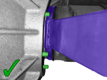
  5. Use the axle extractor tool to release the driveshafts from the transmission.
    Caution: Ensure that the axle extractor tool does not contact any of the differential retaining studs.
    Caution: Do not let the driveshafts rest on the input seal.
    Tip: It might be helpful to loosen the nut that secures the upper link to the subframe. This provides additional clearance when installing the driveshafts.
  6. Secure the gantry bolts (x3) to the drive unit.
    Note: Secure the short bolt to the motor section of the drive unit.
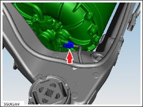
  7. Loosen the nuts that secure the front and rear motor mounts to the subframe (torque 90 Nm).
  8. Loosen the bolts (x3) that secure the motor to the side motor mount. (torque 22 Nm).
    Tip: It might be helpful to only use the gantry bolt that secures to the motor. This allows the drive unit to be rotated to better align the bolt holes.

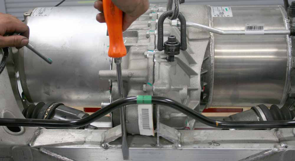
Tip: When removing the bolts that secure the front and rear motor mounts, it might be helpful to use a screwdriver or small prybar to pry against the subframe. This helps to align the bolt holes in the motor mounts with the subframe so that the bolts can be easily removed.

  1. Remove the bolt that secures the front motor mount (torque 90 Nm).
  2. Remove the bolt that secures the rear motor mount (torque 90 Nm).

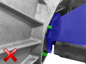
Caution: While lifting the drive unit assembly in the next step, have an assistant brace a screwdriver or similar tool against the subframe and hold the sway bar out of the way. Do not brace the tool against the motor mount.

  1. Carefully lift the drive unit assembly, making sure to clear the rear of the subframe.
    Caution: Do not damage the motor encoder plastic housing.

Installation

Installation procedure is the reverse of removal, except for the following:
Caution: Replace all nylon-insert locknuts.
Caution: Ensure that the new driveshaft has a snap-ring already installed. If it does not, then install a different driveshaft that has a snap-ring already installed. Return any driveshafts without a snap-ring using the MRB process. Do not remove or reuse snap-rings.
  • When installing the driveshaft into the drive unit:
    • Ensure that the opening of the snap ring is facing towards the bottom of the drive unit.
    • Do not damage or displace the oil seal.
    • Verify that the driveshaft is fully seated by carefully pushing it into the drive unit until there is an audible "click" from the snap ring.
  • If both the front and rear drive units were removed at the same time, the vacuum refill tool must be used to refill the cooling system (refer to procedure).
  • Refill the gearbox with the recommended fluid.
  • Transfer the vehicle to a 4 post lift (refer to procedure).
  • Air suspension only: Set the suspension height to “Normal”.
  • Caution: Only fully tighten suspension nuts and bolts when the vehicle is on a 4-post lift and the suspension is in the ride height position.
  • Perform a four wheel alignment (refer to procedure).
  • Use Toolbox to update or redeploy the firmware:
    • If the vehicle is not running the latest firmware, run the "Vehicle Firmware Update" procedure.
    • If the vehicle is running the latest firmware, run the "Firmware Redeploy" procedure.