-
Ensure that the front road wheels are in a straight ahead position.
-
Lock the steering wheel in position.
-
Remove the underhood storage unit (refer to
procedure).
-
Remove the bolt that secures the lower intermediate shaft to the steering rack
(torque 49 Nm).
-
Release the lower intermediate shaft from the steering rack.
-
Raise and support the vehicle (refer to
procedure).
-
Remove the front road wheels (refer to
procedure).
-
Remove the front aero shield panel (refer to
procedure).
-
If the vehicle is equipped with the 2nd generation air conditioning
compressor:
-
Remove the front skid plate (refer to
procedure).
-
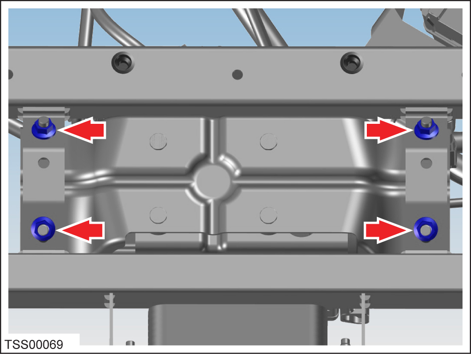
Working beneath the vehicle, remove the nuts (x4) that secure the
compressor and bracket assembly to the front subframe (torque 10 Nm).
-
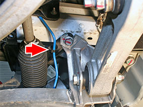
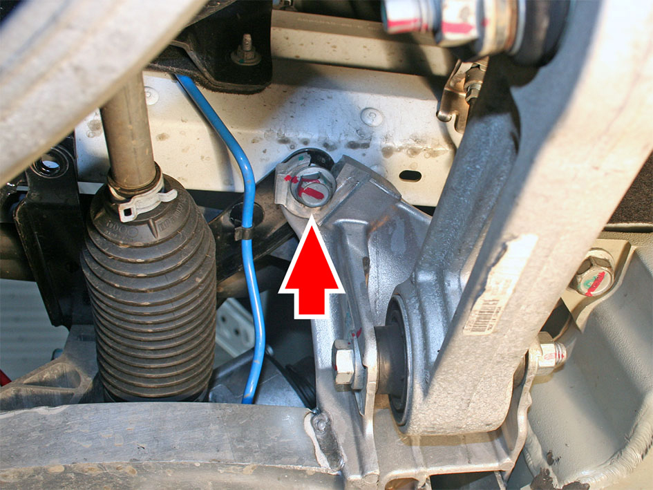
If the vehicle is equipped with air suspension, release the blue air line from
the clip at the LH side of the subframe.
-
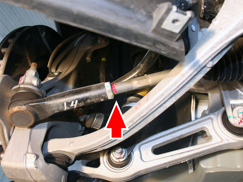
Mark the position of the LH tie rod end.
Tip: An alternative to marking the position of the tie rod end is to
record the number of turns required to remove it in step 16.
-
Loosen the LH tie rod end jam nut (torque 70 Nm).
Caution: To prevent tie rod damage, always restrain
the tie rod with a wrench when loosening or tightening the jam nut.
-
Remove the bolts (x2) that secure the LH sway bar bracket to the subframe
(torque 23 Nm).
-
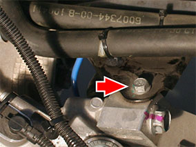
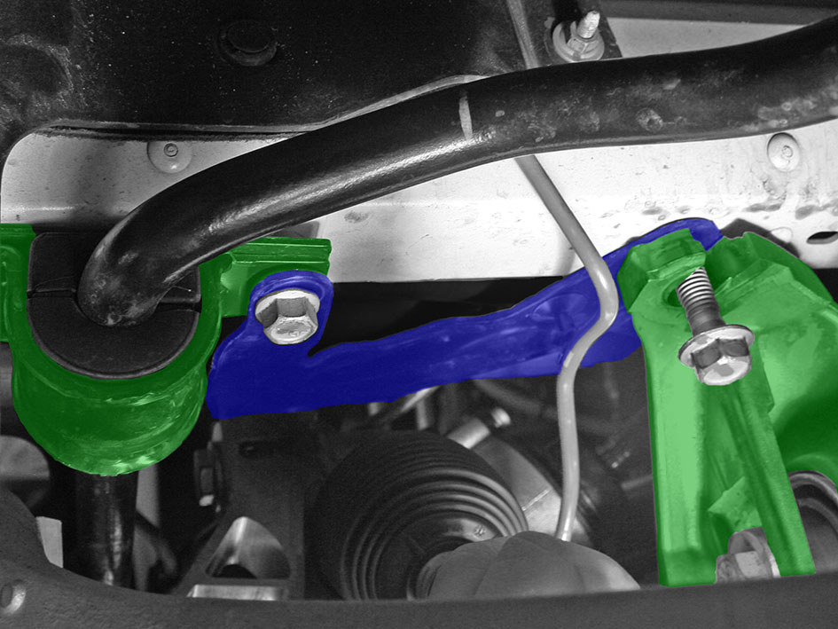
Remove the LH middle subframe bolt (torque 76 Nm).
-
Restrain the LH tie rod ball joint pin with a wrench and remove the nut that
secures the tie rod end to the knuckle (torque 103 Nm).
Caution: To prevent ball joint damage, always hold
the ball joint pin with a wrench while loosening or tightening the lock
nut.
-
Release the tie rod end from the knuckle.
-
Recording the number of turns required, unscrew the LH tie rod end from the tie
rod.
Note: Either mark the position of the tie rod end before removal, or record the
number of turns required to remove it.
-
Remove the jam nut from the tie rod.
-
Working from the RH side, pull the tie rod all the way out, as if the steering
wheel was turned completely to the right.
-
Repeat steps 10-17 on the RH side.
-
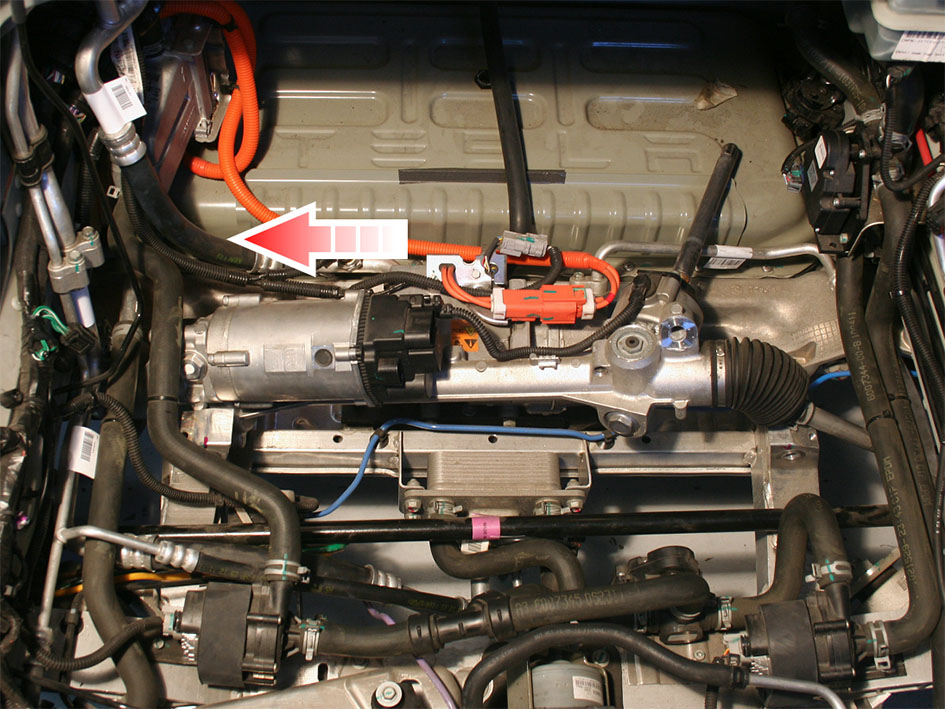
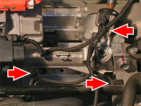
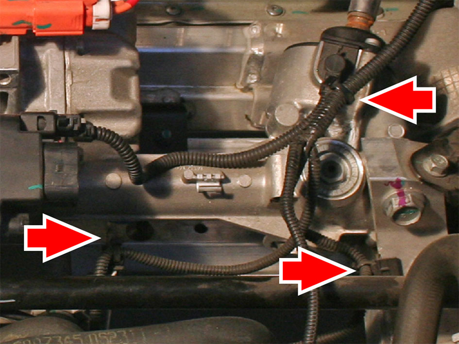
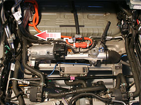
Disconnect the front electrical connectors (x2) from the steering rack.
-
Release the fir tree clips from the LH and RH subframe braces.
-
Remove the upper bolts (x2) that secure the LH and RH subframe braces to the
subframe (torque 26 Nm).
-
Remove the LH and RH subframe braces.
-
If equipped, disconnect the electrical connector from the TXV valve.
-
If equipped, disconnect the electrical connector from the 3 way coolant
valve.
-
Disconnect the edge clips (x2) and fir tree clip that secure the harness to the
LH side of the steering rack and subframe, then move the harness out of the
way.
-
If the vehicle is equipped with the 2nd generation air conditioning compressor,
move the compressor and bracket assembly toward the rear of the vehicle.
Note: Do not disconnect the refrigerant lines from the compressor.
-
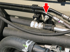
Remove the nut that secures the A/C discharge line bushing hanger to the side
member, then release the bushing hanger from the stud.
-
Disconnect the electrical connector from coolant pump 2.
Note: Coolant pump 2 is on the LH side of the vehicle.
-
Release coolant pump 2 from its rubber mount.
Note: Do not disconnect the coolant hoses from the pump.
-
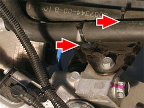
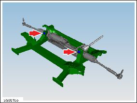
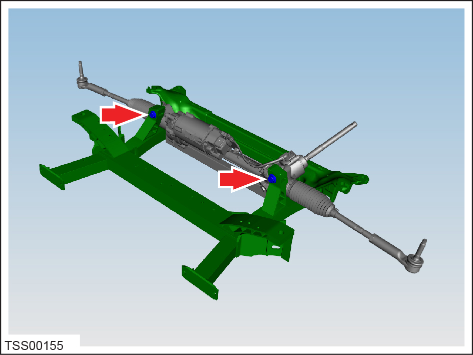
Remove the bolts (x2) that secure the steering rack assembly to the subframe
(torque 175 Nm).
Note: Record the positions of any shims.
Note: The following steps require 1 technician working in the RH wheelwell area, and
1 technician working in the underhood area.
-
Rotate the rack toward the rear of the vehicle, then slide the rack toward the
RH of the vehicle.
-
Rotate the LH tie rod toward the front of the vehicle.
-
Maneuver the LH tie rod around the hoses and pipes on the LH of the
vehicle.
-
Remove the steering rack through the underhood area.
Tip: If the RH coolant hose interferes with removal of the steering
rack, release the bolts (x2) that secure the 3 way coolant valve bracket to the
subframe.