Removal
Warning: Perform all of the voltage checks listed in the procedure. If
any voltage reading is more than 10V, the high voltage contactors are not fully
opened. Due to the risk of electrocution, contact Service Engineering before
performing any further work.
-
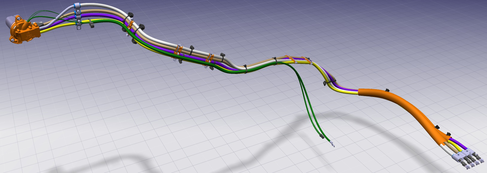
Starting from the front and working toward the rear of the vehicle, mark
the 4 HV cables that lead to the charge port from front to rear as L2, L3,
L1, and N.

-
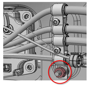
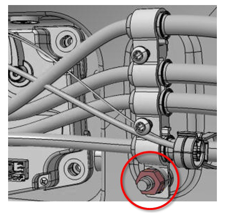
Release the nut that secures the grounding wire from the charge port
(torque 6 Nm).

-
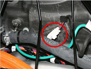
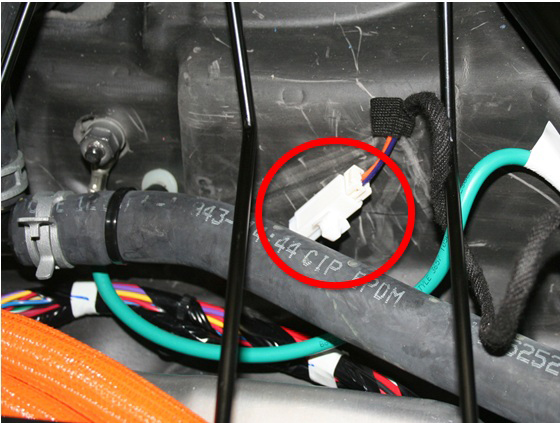
Disconnect the proximity detection harness.
-
Remove the grounding bracket by releasing the nut that secures it to the body.
- Single phase (North America, Japan): torque 6 Nm
- 3 phase (Europe, APAC): torque 9 Nm
-
Remove the cover from the cable connector by using a trim tool or similar
non-conductive tool to bend the 3 tabs that secure the cover to the cable
connector.
Note: The locations of the tabs are marked by arrows on the face of the cover.Caution: Do not lose or damage the magnet on the outboard side of the cable connector.

-
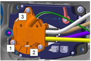
Remove the 3 bolts that secure the cable connector to the charge port in the
order shown. Remove the cable connector from the charge port.
- Single phase (North America, Japan): torque 4 Nm
- 3 phase (Europe, APAC): torque 5 Nm


Caution: Even though the HV harness is accessible, do not
attempt to remove it at this time.
Note: Before performing the next step, note the locations of the clips that
secure the HV harness to the 2nd row seat frame. During installation of
the new HV harness, ensure that the harness is clipped to the seat frame
in the same locations.
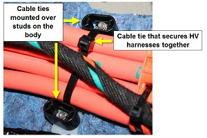
Caution: Before performing the next step, examine the cable ties on
the HV harness. Note that some of the cable ties are mounted to studs on the
body.
-
Release the cable tie mounts that secure the harness to the studs on the
body.
-
Remove the harness assembly from the vehicle.