Frame - Panoramic Roof Assembly (Remove and Replace)

FRT No: 24102002

Warning: To avoid personal injury, wear cut-resistant gloves when performing this operation.

Special tools required for this procedure:

Supplier Part Number Description
Tesla 1078739-00-A Equalizer Hydroblade Tool
Tesla 1078806-00-A GripTite Wire Cutting Tool
Tesla 1078736-00-A Squire Auto Glass Cut-Out Wire
Tesla 1077016-00-A Carbide Burr
Tesla 1077452-00-A Pneumatic Die Grinder
Tesla 223-28550-TSL Torque Screwdriver, 1-6 Nm

Removal

  1. Remove the panoramic roof sliding glass (refer to procedure).
  2. Remove the LH side applique:
  3. Remove the RH side applique.
  4. Remove the panoramic roof fixed glass (refer to procedure).
  5. Remove the front applique:
  6. Remove the LH footwell cover:
  7. Remove the RH footwell cover:
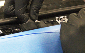
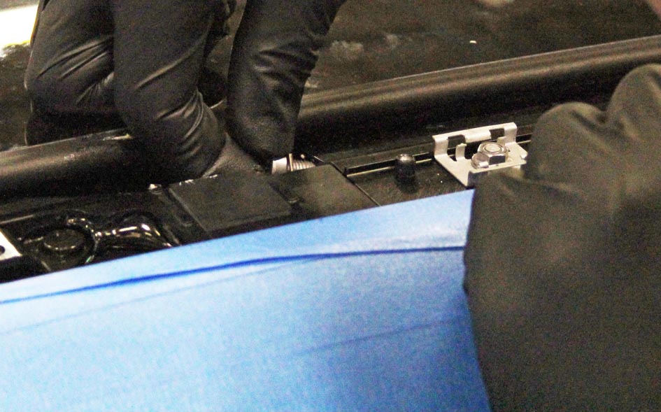
  8. Loosen the sunroof motors:
    1. If the vehicle is equipped with premium audio, remove the bolts (x3) that secure the premium boost amplifier module bracket to the front cross car beam (torque 6 Nm).
    2. Loosen the screws (x3) that secure the LH sunroof motor to the dash frame (torque 5 Nm) and pull the LH sunroof motor away from the motor block to release the cable.
    3. Remove the glove box assembly (refer to procedure).
    4. Loosen the screws (x3) that secure the RH sunroof motor to the A-pillar (torque 5 Nm) and pull the RH sunroof motor away from the motor block to release the cable.
  9. Lower the headliner and support it on the seats (refer to procedure).
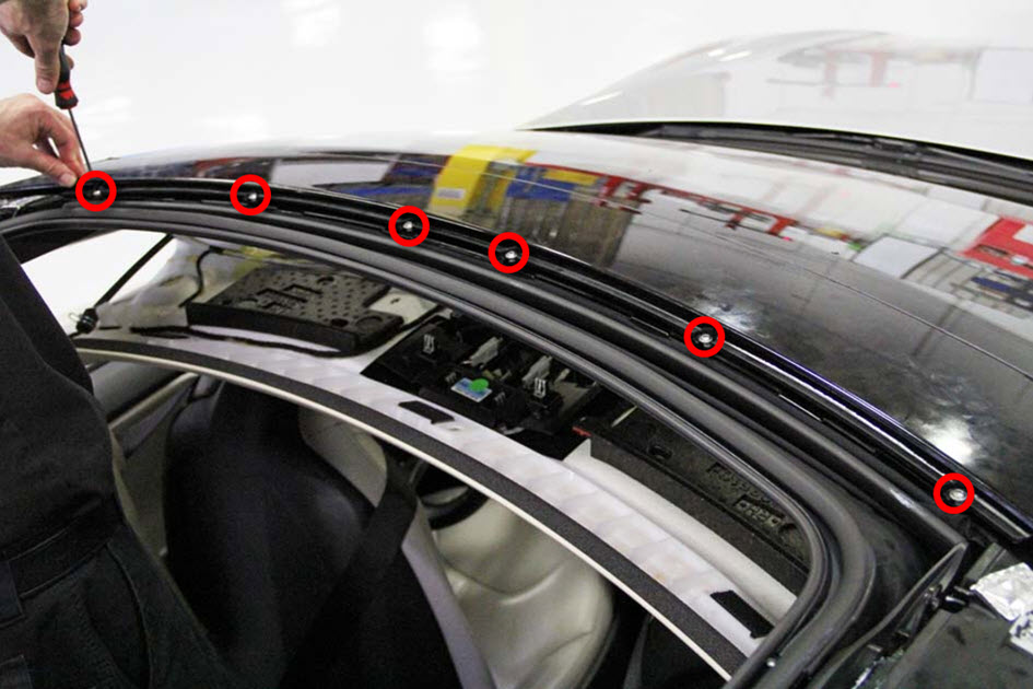
  10. Remove both rear drive links and cables:
    Note: Perform this step on both sides of the vehicle.
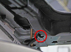
    1. Remove the drive cable stop screw.
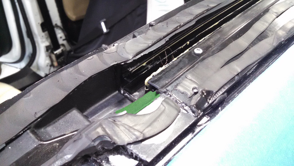
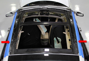
    2. If necessary, remove the grey foam block (highlighted in green) at the rear of the drive cable channel.
    3. Remove the rear links.
    4. Remove the drive cables from the guide tubes.
      Note: The cables tend to get hung up at the point in the drive channel where the stop screw was located.
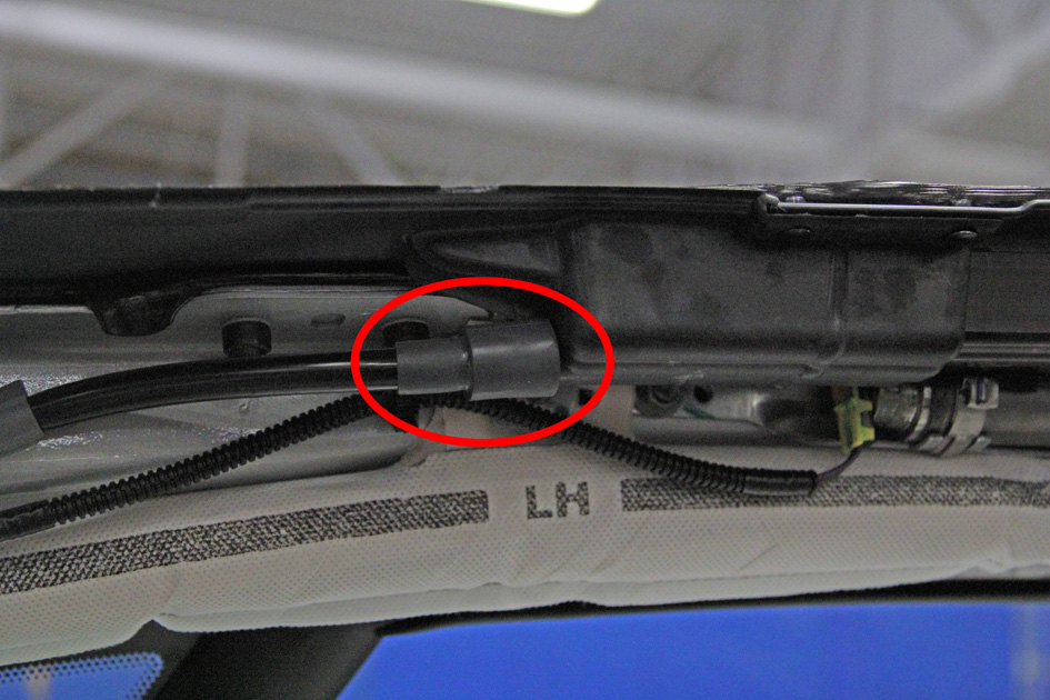
  11. Release the front drain tubes (x2) from the roof assembly.
  12. Release the rear drain tubes (x2) from the roof assembly.
  13. Disconnect the pinch sensor electrical connector located on the RH side between the A-pillar and B-pillar.
  14. Disconnect 12V power.

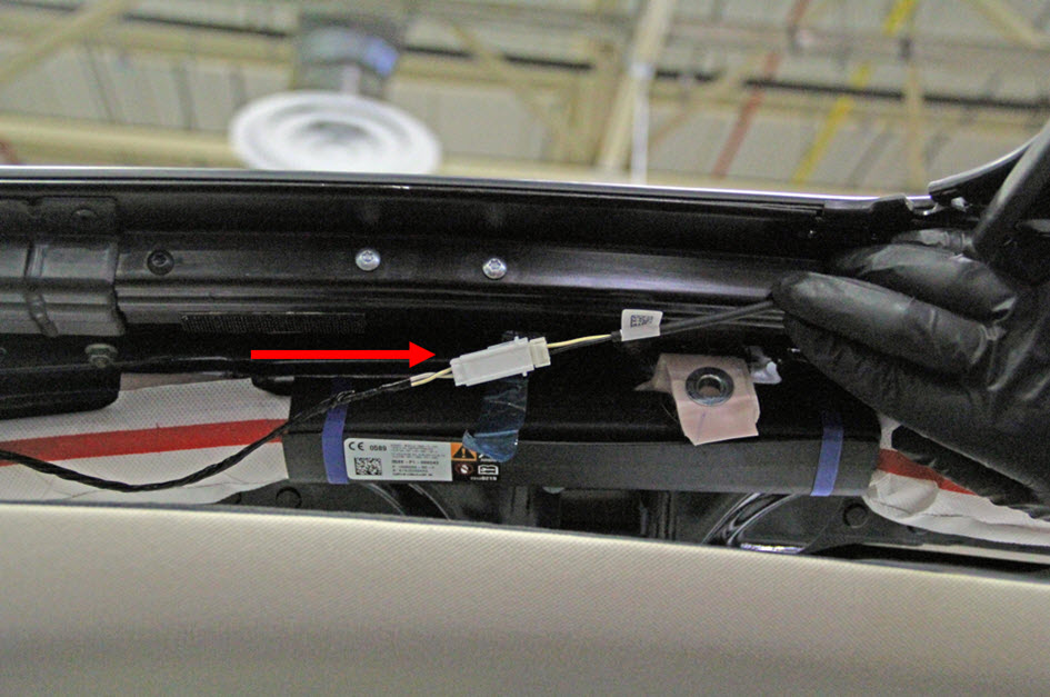
Caution: Ensure that the first responder loop has been disconnected for at least 2 minutes before continuing this procedure.

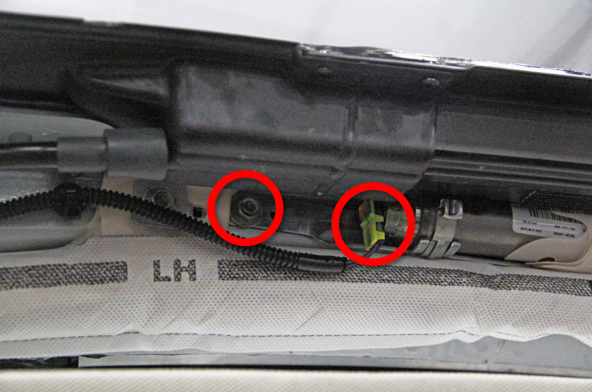
  1. Unplug the electrical connector for the curtain airbag canister and remove the rear bolt that secures the curtain airbag canister (torque 10 Nm) so that the cannister can be moved away from the work area.
  2. Remove the caps from the roof rack anchor nuts and then remove the roof rack anchor nuts (x4, 2 per anchor) (torque 11 Nm). Remove the roof rack anchors (x2).
    Note: Cut away any adhesive that is holding in the anchors as necessary.
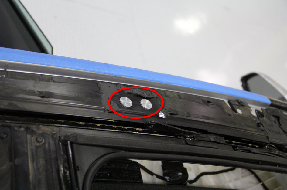
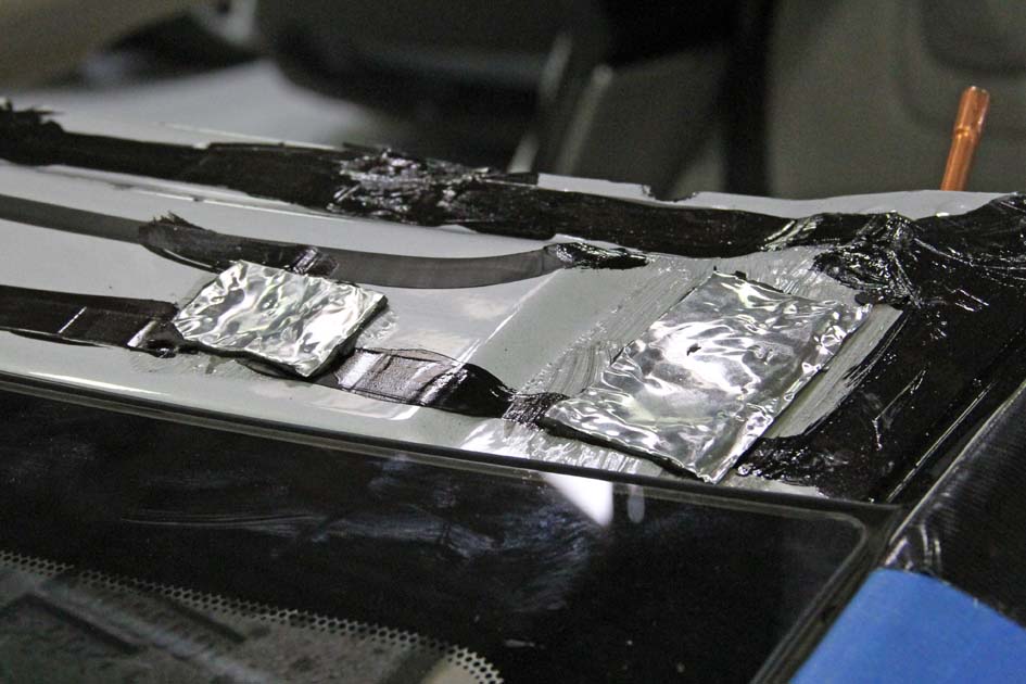
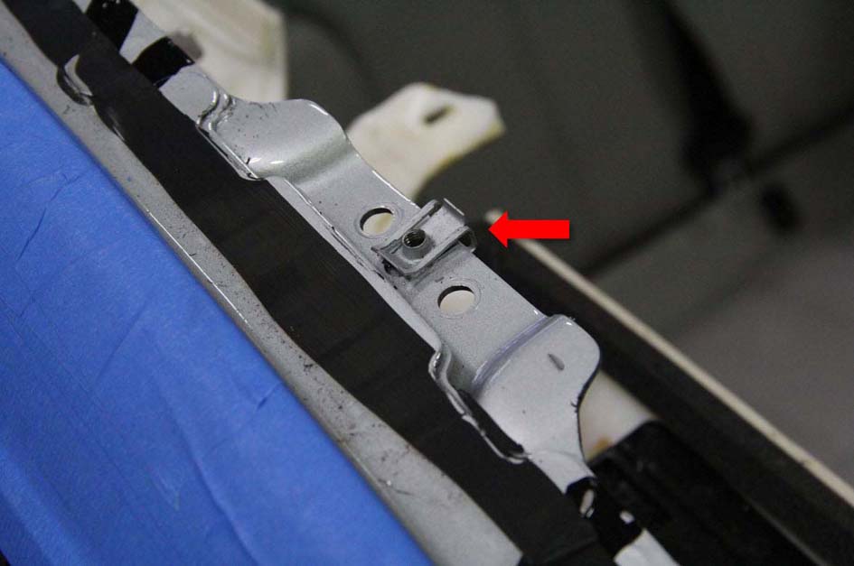
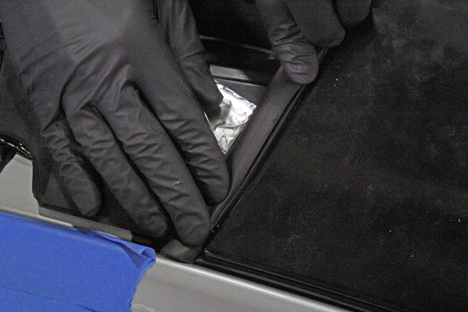
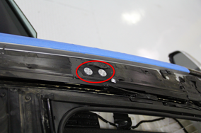
  3. Remove the butyl patches and the threaded inserts (x2) from the roof frame.
  4. Repeat steps 15-18 on the other side of the vehicle
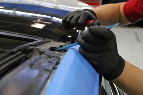
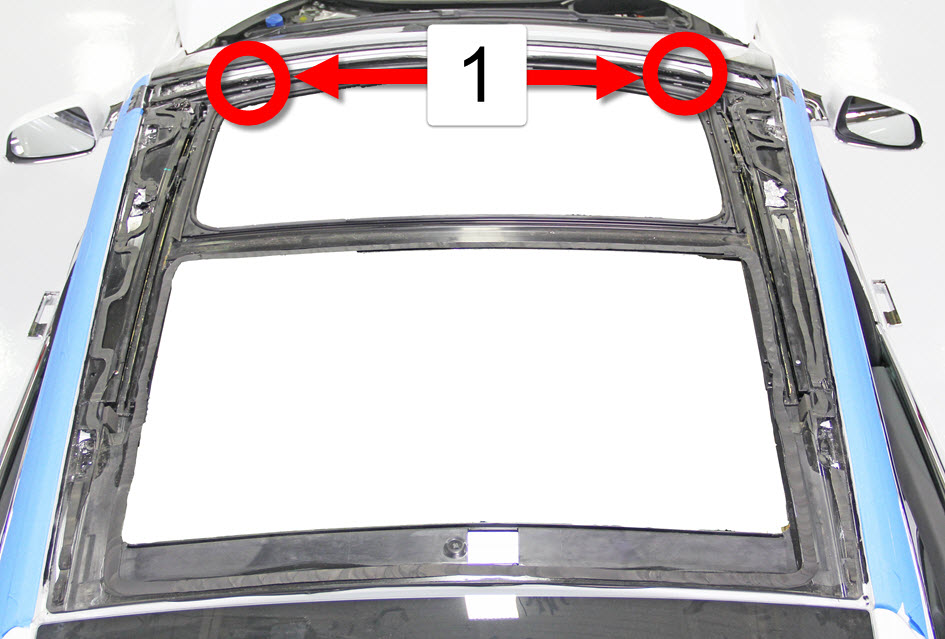
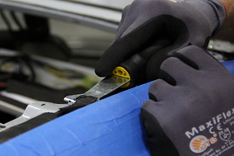
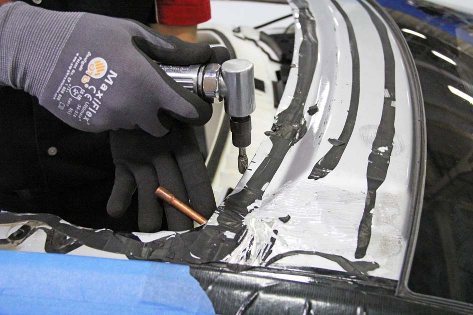
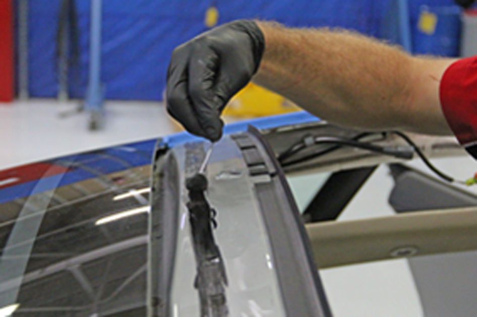
  5. Starting at the center of the front section of the roof frame and moving toward the sides, use a hydroblade tool to carefully cut through the adhesive.
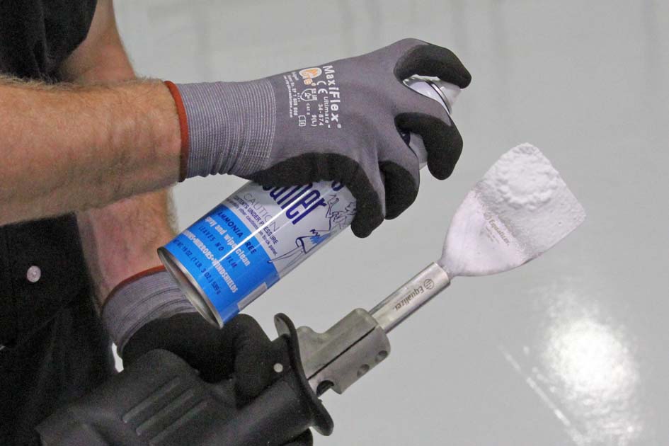
    Caution: Take care not to damage the copper guides.
    Note: Lubricate the blade with water during this step, or spray the blade and the work area with glass cleaner.
    Note: The center portion of the frame overlaps above the side portions.

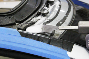
    1 Locations the center portion overlaps above the side portion
  6. Cut an appropriate length of square wire and insert the wire into the square wire cutting tool.
  7. Push the tool through the adhesive at the roof rack bracket cutaway. Pull the wire through and remove the tool.
  8. Connect the T-handles to the wire.
    Note: The remainder of the removal procedure requires an assistant.
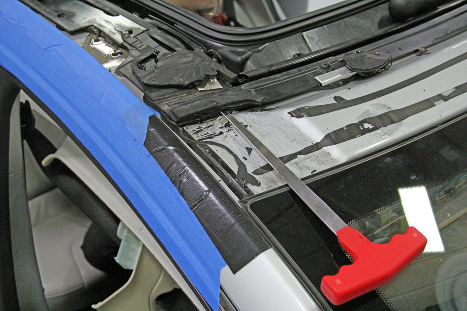
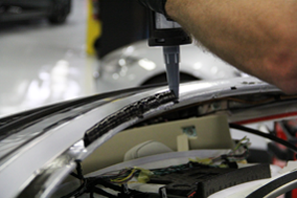
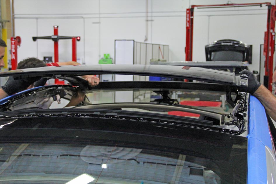
  9. Cut through the adhesive at the rear section of the roof frame with the cutting tool and then cut through the adhesive at the side sections. Use a flat tool to guide the wire underneath the frame as it changes direction or level.
    Warning: To avoid personal injury, eye protection must be worn when performing this operation.
    Warning: Only use cleaning agents and solvents in a well-ventilated area.
    Caution: The technician inside the vehicle should use a flashlight and a wedge tool to guide the wire, making sure not to apply too much downward pressure on the wire. Too much pressure might result in the wire cutting through the pinch weld.
    Caution: Take care not to damage component(s).
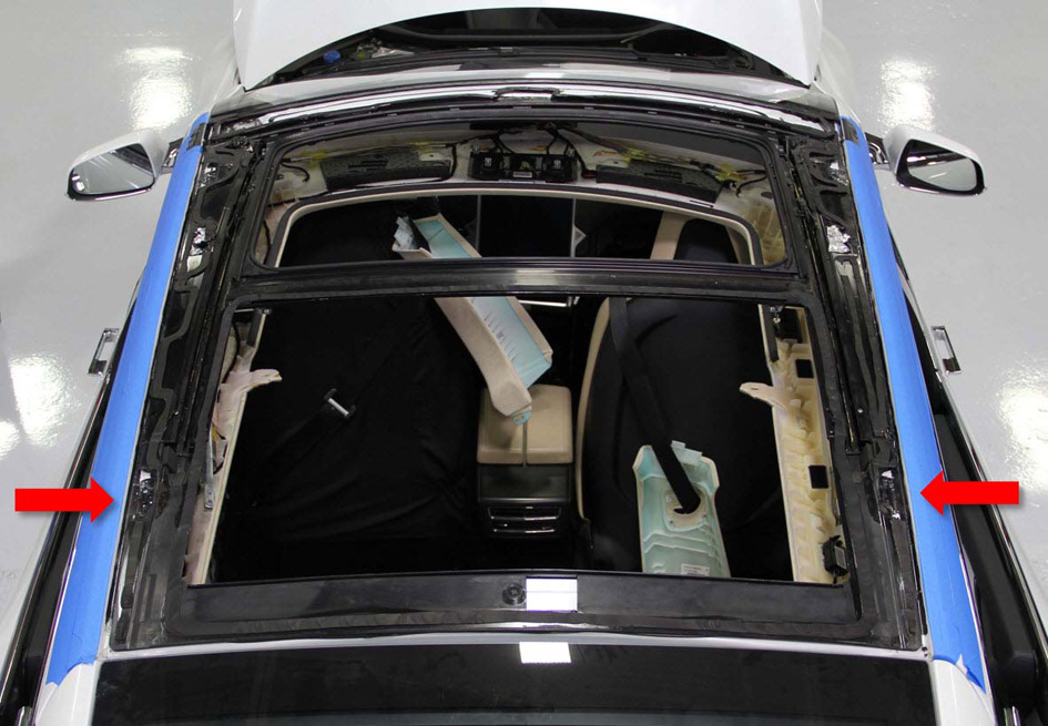
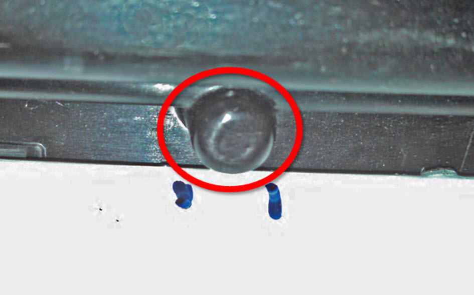
    Note: In several locations, the body and roof frame dip slightly and there is minimal clearance between the frame and the body, which can make it difficult to get the wire to pass though those points. Use a flat tool to help guide the wire between the body and the roof frame.
    Note: On 1st generation panoramic roofs, the wire might get stuck on a speed nut in front of the middle header. Use a flat tool to help guide the wire between the body and the roof frame.
    Note: On each side of the frame two metal rivets protrude from the bottom of the roof frame. These rivets can be hard to cut through. Use a wedge tool to hold the cutting wire firmly against the body to guide it underneath the riveted area. Alternatively, use a flat metal tool to cut some of the adhesive near the rivets to provide a path for the wire.
    Note: At the center of the rear section, a locator post protrudes downward from the roof frame. Pry up the roof frame to guide the wire under the datum peg. Alternatively, hold the bottom of the locator post while cutting it, and remove it. Do not allow the locator post to fall into the roof channel.
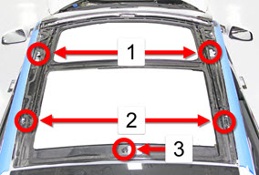
    1 Locations where frame dips slightly
    2 Locations where frame dips slightly and has 2 metal rivets
    3 Location of locator post
  10. Remove the panoramic roof frame from the vehicle.

Installation

  1. Use a scraping tool to remove the majority of the adhesive from the body, leaving a smooth layer of the original adhesive approximately 1 mm thick or less.
  2. Remove all existing butyl patches and replace them with new ones.
  3. Vacuum any debris around the roof frame area.
  4. Remove the drive link stops from the new roof frame.
  5. Remove the drive cables and links from the new roof frame.
  6. If retrofitting a 2nd generation panoramic roof frame onto a vehicle that originally had a 1st generation panoramic roof frame, remove the curtain airbag nut clips from the body.
  7. 2nd generation roof frames: Loosen the front applique screws (x6) and remove the front applique.
  8. Test fit the new roof frame and the fixed glass.
    Caution: Make sure that the front and rear datum pins are placed properly.
  9. If retrofitting a 2nd generation panoramic roof frame onto a vehicle that originally had a 1st generation panoramic roof frame, modify the vehicle body:
    1. Mark the bottom of the front header for the notches (x6) that need to be cut.
    2. Remove the new roof frame.
    3. Transfer the marks from the bottom to the top of the front header.
    4. Install a protective cover over the front of the headliner and the interior.
    5. Use a die grinder with a carbide burr bit to create notches in the header panel that are approximately 5 mm (3/16 in) deep (x6) in the locations marked previously.
    6. Vacuum all debris.
    7. Remove the protective cover.
    8. Test fit the new roof frame with the fixed glass and verify that the notches line up.
      Tip: Use a mirror to make it easier to see the notches.
    9. Remove the new roof frame.
  10. Loosely install the roof rack anchors.
  11. Vacuum the top of the headliner.
  12. Install the finisher at the rear of the roof opening by sliding the groove of the finisher over the edge of the body panel.
  13. Wipe all of the sealing surfaces with isopropyl alcohol (IPA) or with alcohol wipes.
  14. Apply primer to all adhesive paths on the body and all roof components, and on any bare metal on the body opening.
    Caution: Check the expiration date of the primer and adhesive before use.
    Caution: Check the primer and adhesive packaging for the appropriate working times for each product. Prepare the necessary tools and work environment so that the the frame can be installed within the specified working times.
    Note: The procedures requires approximately 4 tubes of adhesive.
  15. Assemble the adhesive applicator.
  16. Cut the tip of the adhesive applicator so that it will produce a bead 8 mm (5/16 in) wide and 14 mm (9/16 in) high.
  17. Apply adhesive to the vehicle body over the existing adhesive.
    Caution: To avoid gaps where water might penetrate, start the bead at the front or the back of the body (not the sides).
  18. With assistance, position and align the new roof frame to the body. Put the existing copper guide tubes at the front into the new roof frame. Evenly and progressively press the frame onto the spacers.
  19. Measure the gaps between the new roof frame and the body on each side, and adjust the frame so that the gaps are even on each side.
  20. Apply adhesive to the new roof frame in the area for the fixed glass.
    Caution: To avoid gaps where water might penetrate, start the bead at the front or the back of the frame (not the sides).
  21. Test fit the fixed glass to ensure that it sits flush to the roof frame.
  22. Install the fixed glass.
    Caution: Make sure that the front and rear datum pins are placed properly.
  23. Apply suitable tape or weights (such as sand bags) to hold the frame in place while the adhesive cures.
    Caution: Do not drive the vehicle until the adhesive has cured. Refer to the adhesive packaging for the safe drive-away time.
  24. Examine the integrity of the whole length of the adhesive joint and add more if required.
  25. Clean off any excess adhesive extruded from the joint.
  26. Install the bolts (x4) (torque 10 Nm) to secure the frame to the body.
  27. For 1st generation frames: Install butyl patches over the centering bolts.
  28. Install the drive links and cables into the new roof frame.
    Note: The end of the LH drive cable is red; the end of the RH drive cable is yellow.
  29. Slide each link forward to align with the notch to provide room to insert the red drive link stops. Slide the links back and position the blocks. Secure each block with 2 screws from inside the cabin (torque 10 Nm).
  30. Remove the protective tape from the sides of the vehicle.
  31. Apply adhesive along the path indicated by the lines on the underside of the front applique.
  32. With assistance, slide the front of the front applique under the body panel.
  33. For 2nd generation frames: Install the screws (x6) that secure the rear of the applique to the roof frame (torque 1 Nm).
    Caution: Be careful not to cross-thread or over-torque the screws.
  34. Install the front applique seal by pressing it into the applique, starting from one of the ends.
    Note: Use P-80 emulsion if the seal does not easily go in all the way.
  35. Apply suitable tape or weights (such as sand bags) to secure the applique, especially the back corners, while the adhesive cures. Continue to the next step.
    Caution: Make sure that the corners of the applique are flush with the body.
  36. Install the side appliques.
  37. Wipe the adhesive path with alcohol wipes.
  38. Install the panoramic roof sliding glass assembly (refer to procedure).
    Note: Start the rear screws (x2) before installing the front screws (x2).
  39. Install the curtain airbag cannisters and reconnect the electrical connectors to the airbag cannisters.
    Note: If retrofitting a 2nd generation panoramic roof frame onto a vehicle that originally had a 1st generation panoramic roof frame, install the curtain airbag mounting bolt in the rearward hole.
  40. If retrofitting a 2nd generation panoramic roof frame onto a vehicle that originally had a 1st generation panoramic roof frame, replace the sunroof controller module:
  41. Connect the 12V negative terminal and the First Responder Loop.
  42. Secure the sunroof motors.
  43. Install the footwell covers.
  44. Install new roof rack anchors (x4) with nuts (x2) (torque 11 Nm).
  45. Connect the front drain tubes.
    Note: Rotate the hose ends to aid in installation.
  46. Connect the rear drain tubes.
  47. Connect the pinch sensor harness connector and secure the connector to the roof with a cable tie.
    Caution: Use caution with the wire routing near the side curtain airbag.
    Note: If retrofitting a 2nd generation panoramic roof frame onto a vehicle that originally had a 1st generation panoramic roof frame, install the pinch sensor adapter harness between the connectors (x2) of the new roof frame and the vehicle pinch sensor harness.
  48. Install the bolts that secure the drive cable tubes.
  49. Install the headliner (refer to procedure).
    Note: If retrofitting a 2nd generation panoramic roof frame onto a vehicle that originally had a 1st generation panoramic roof frame, install a new panoramic roof middle cover.
  50. Calibrate the panoramic roof (refer to procedure).
  51. Test the sliding glass assembly in all positions, and open and close it several times.
  52. Perform a vehicle test drive, listening for any creaks or rattles from the roof, headliner, or instrument panel.